
Semiconductor solid illuminator and the method thereof

Inactive Publication Date: 2011-02-03
THERMOKING TECH INT
View PDF5 Cites 11 Cited by
  • Summary
  • Abstract
  • Description
  • Claims
  • Application Information

AI Technical Summary

Benefits of technology

[0010]Another object of the present invention is to provide a semiconductor solid illuminator in which, because the heat-dissipating body is disposed below the illuminant, such design can enhance the heat-dissipating effect due to the fact that cooler air may quickly rise up to fill the void or vacuum created by the hotter air, which continuously travels upwards, and can bypass the undesirable factors (such as the accumulation of dusts) that may impede the heat-dissipating effect.
[0011]To reach these objects, the semiconductor solid illuminator and such method of the present invention are disclosed. The semiconductor solid illuminator of the present invention comprises a heat-dissipating body, at least an illuminant and a lamp shade. The heat-dissipating body has a conjoint surface. The illuminant is disposed on top of the conjoint surface. A plurality of heat-dissipating fins extend from the edge or lower surface of the heat-dissipating body. The lamp shade is fitted on top of the heat-dissipating body. A reflecting layer is provided on the inner surface of the lamp shade by the ordinary coating method or electroplating. Bright light emitted from the illuminant is reflected by the reflecting layer of the lamp shade and then travels downwards so that such light is mellowed or softened and would not shine on our eyes directly. In addition, heat generated by the illuminant is transferred to the heat-dissipating body and then to the heat-dissipating fins, through which the heat is dissipated into the air. Therefore, heat may be dissipated quickly. Because the heat-dissipating body is disposed below the illuminant, such design can enhance the heat-dissipating effect due to the fact that cooler air may quickly rise up to fill the void created by the hotter air, which continuously travels upwards, and can bypass the undesirable factors (such as the accumulation of dusts) that may impede the heat-dissipating effect.
[0012]Moreover, a heat-conducting body is provided in the heat-dissipating body so that heat may be transferred to the lamp shade more quickly and so as to quickly dissipate the heat.

Problems solved by technology

However, they have the following disadvantages:(1) In the prior art, bright light emitted from LED or OLED is used for illumination and such bright light is too bright and can dazzle us.(2) In the prior art, heat is first transferred to a portion above the LED or OLED and then to several heat-dissipating fins, from which heat is dissipated into the air.
Many undesirable factors (such as the accumulation of dusts and birds' droppings) may impede the heat-dissipating effect and may even damage the illuminator.

Method used


Image

  • Semiconductor solid illuminator and the method thereof
  • Semiconductor solid illuminator and the method thereof
  • Semiconductor solid illuminator and the method thereof

Examples


Embodiment Construction

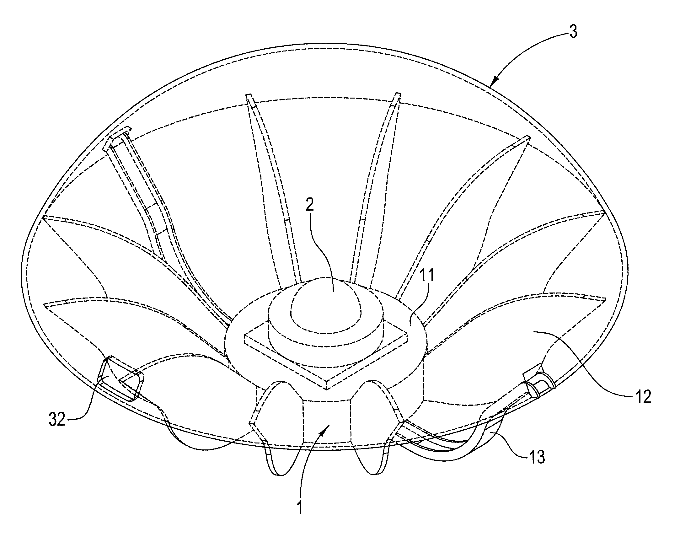
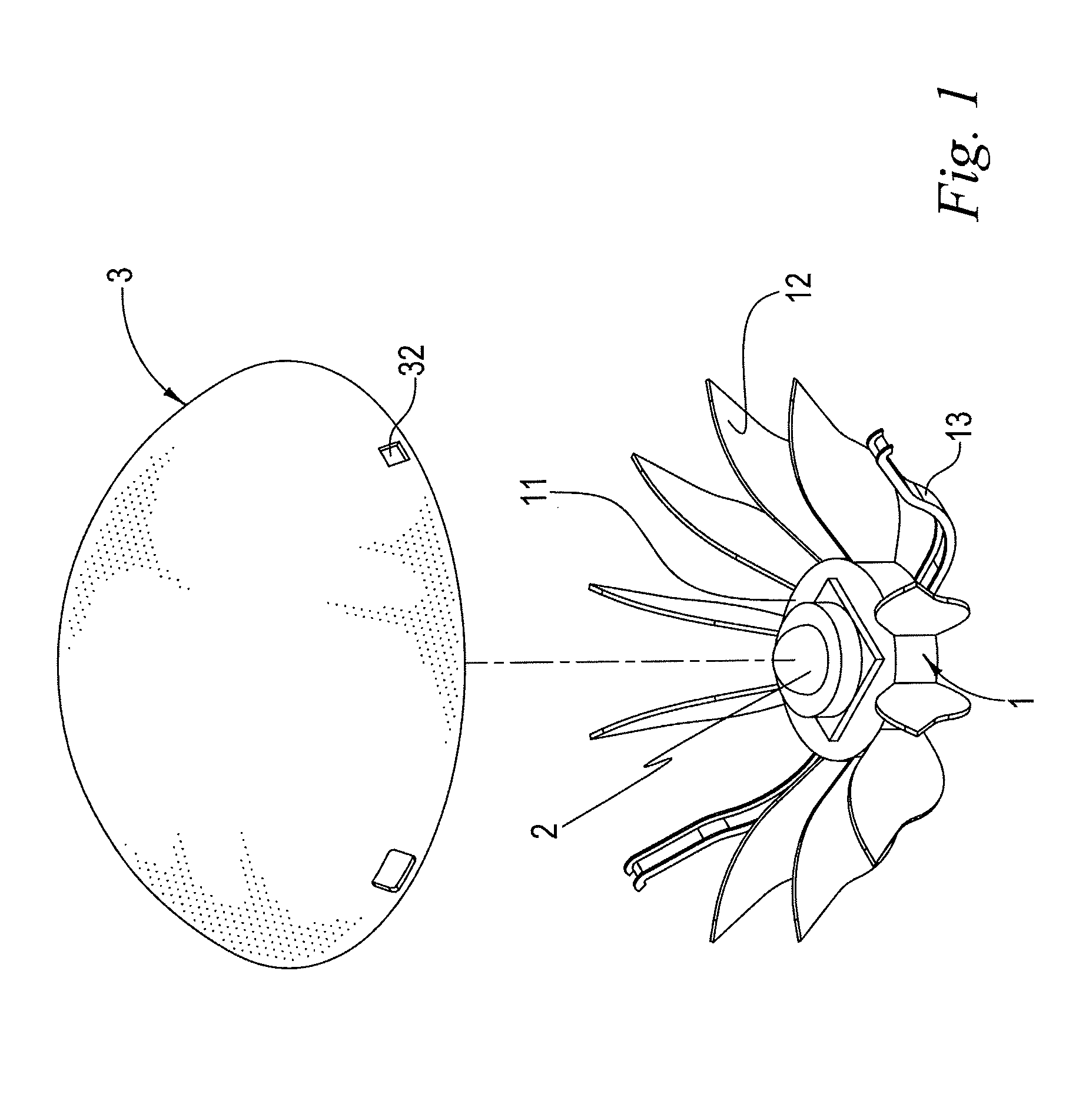
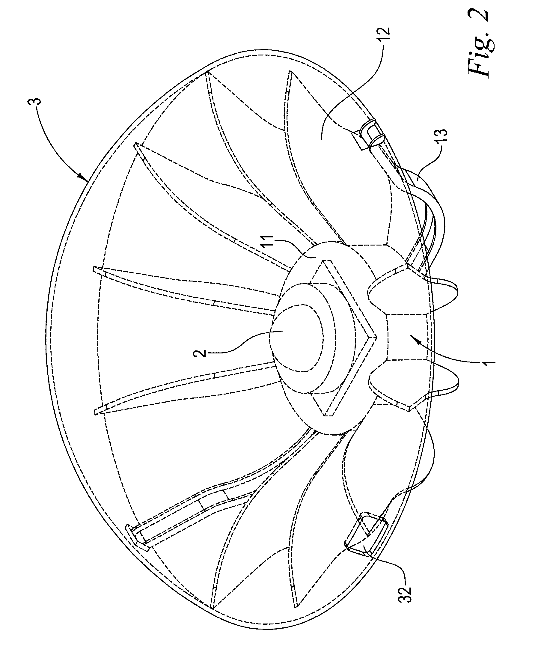
[0019]Please see FIGS. 1, 2 and 3. The semiconductor solid illuminator of the present invention comprises a heat-dissipating body 1, at least an illuminant 2 and a lamp shade 3. The heat-dissipating body 1 has a conjoint surface 11. A plurality of heat-dissipating fins 12 extend from the edge or lower surface of the heat-dissipating body 1. An electric wire slot 13 is provided in the heat-dissipating body 1 to hold an electric wire. The electric wire slot 13 may be integrally formed with the heat-dissipating fins 12. The illuminant 2 is fitted on top of the conjoint surface 11. The illuminant 2 is an LED or an OLED. A reflecting layer 31 is provided on the inner surface of the lamp shade 3 and a plurality of holes 32 are provided in the peripheral body of the lamp shade 3. In assembly, the lamp shade 3 is fitted on top of the heat-dissipating body 1 so as to cover the illuminant 2. The lamp shade 3 is connected with the heat-dissipating body 1 through the engagement of the electric ...


PUM

PropertyMeasurementUnit
Speedaaaaaaaaaa
Heataaaaaaaaaa

Abstract

A semiconductor solid illuminator and such lighting method are disclosed. The semiconductor solid illuminator of the present invention comprises a heat-dissipating body, at least an illuminant and a lamp shade. The heat-dissipating body has a conjoint surface. The illuminant is disposed on top of the conjoint surface. The lamp shade is fitted on top of the heat-dissipating body. A reflecting layer is provided on the inner surface of the lamp shade. Bright light emitted from the illuminant is reflected by the reflecting layer of the lamp shade and then travels downwards so that such light is mellowed or softened and would not shine on our eyes directly.

Description

BACKGROUND OF THE INVENTION[0001]1. Field of the Invention[0002]The invention generally relates to a semiconductor solid illuminator. More particularly, the invention relates to a semiconductor solid illuminator in which bright light emitted from the illuminant is reflected by the reflecting layer of the lamp shade and then travels downwards so that such light is mellowed and would not shine on our eyes directly.[0003]2. Description of the Prior Art[0004]LED and OLED, which can emit bright light, are characterized with long service life and high energy efficiency and are compact, durable, suitable for mass-production and highly responsive. They have been used in illuminators. However, they have the following disadvantages:[0005](1) In the prior art, bright light emitted from LED or OLED is used for illumination and such bright light is too bright and can dazzle us.[0006](2) In the prior art, heat is first transferred to a portion above the LED or OLED and then to several heat-dissip...

Claims


Application Information

Patent Timeline
IPC IPC(8): F21V29/00
CPCF21S8/00F21V7/0008F21V7/045F21V7/22F21V11/06F21V29/773F21V23/002F21V29/004F21Y2101/02F21Y2105/008F21V13/10F21Y2105/00F21Y2115/15F21V7/28F21Y2115/10
Inventor KUAN, HSINNING
Owner THERMOKING TECH INT
Features
  • Generate Ideas
  • Intellectual Property
  • Life Sciences
  • Materials
  • Tech Scout
  • Unparalleled Data Quality
  • Higher Quality Content
  • 60% Fewer Hallucinations
Learn More