
Base station

a base station and radio communication technology, applied in the field of radio communication systems, can solve the problems of reducing the quality of signals and interfering signals with each other

Active Publication Date: 2011-02-03
NTT DOCOMO INC
View PDF4 Cites 12 Cited by
  • Summary
  • Abstract
  • Description
  • Claims
  • Application Information

AI Technical Summary

Benefits of technology

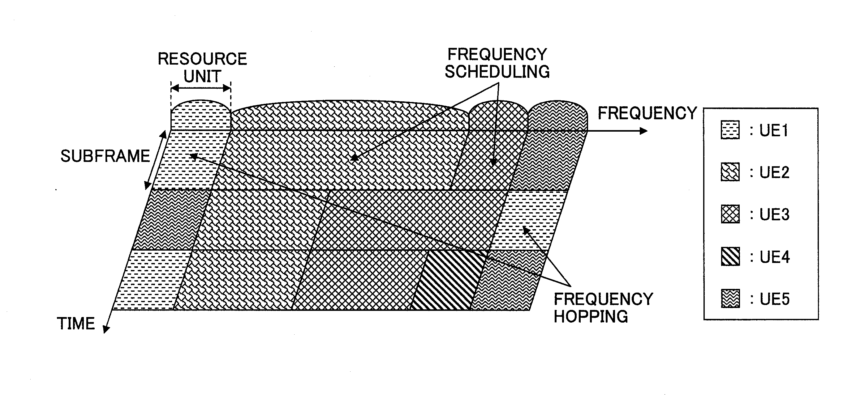
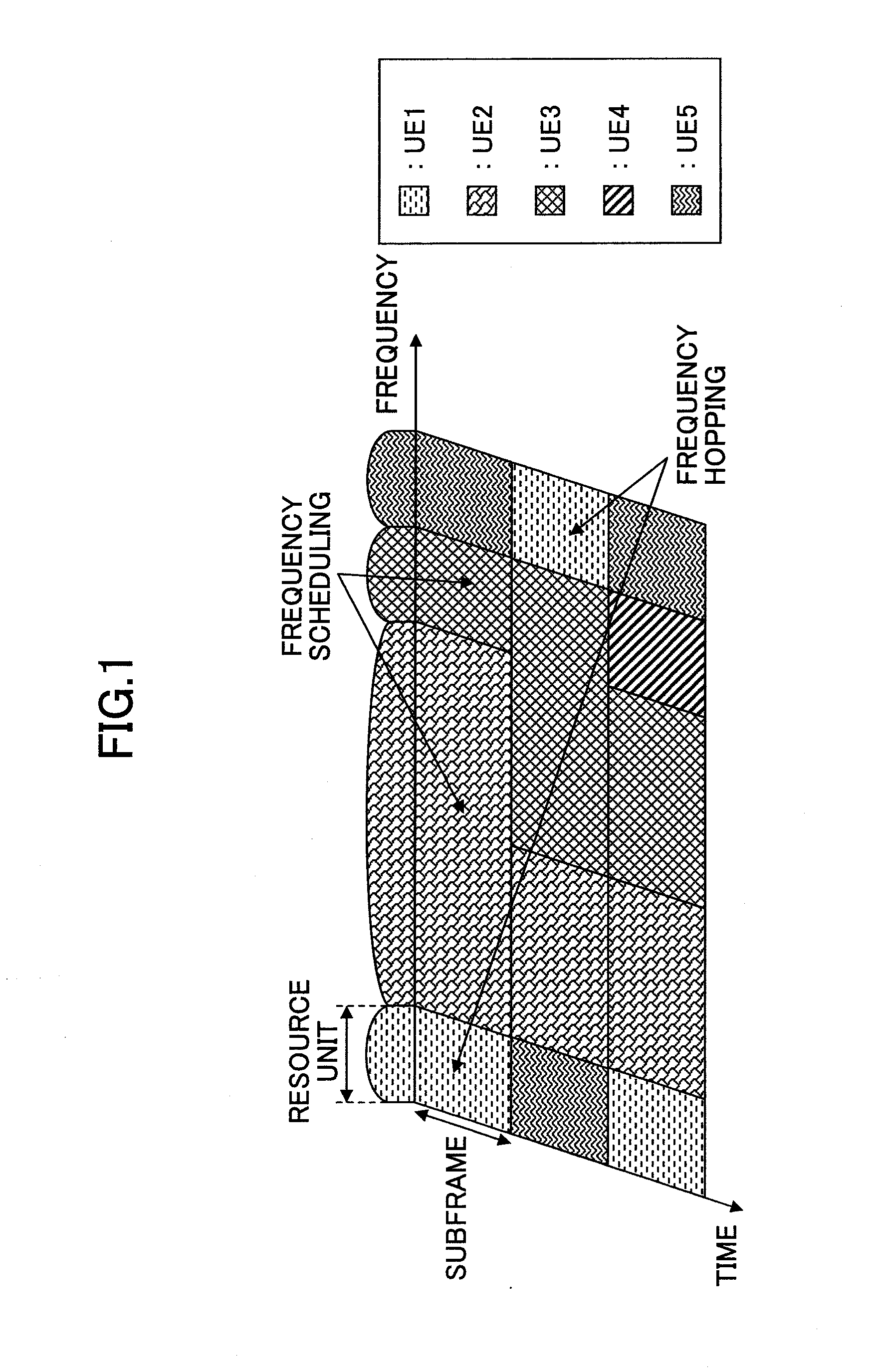
[0014]One aspect of the present invention provides a base station that makes it possible to use frequency hopping for uplink radio access in an E-UTRA system.

Problems solved by technology

If frequency bands allocated in neighboring cells partly overlap each other, signals interfere with each other and their quality is reduced.

Method used


Image

  • Base station
  • Base station
  • Base station

Examples


Embodiment Construction

class="uspto-list-item">204 Uplink-scheduling-grant-signal-transmission-control-signal generating unit[0042]206 Demodulation RS generating unit[0043]208 Synchronization-detection / channel-estimation unit[0044]210 Channel decoding unit[0045]212 Coherent detection unit[0046]214 Uplink-channel-condition estimation unit[0047]216 Scheduler[0048]218 Frequency hopping determining unit[0049]220 Broadcast channel generating unit[0050]400 Core network[0051]500 Physical uplink shared channel[0052]510 Uplink control channel[0053]520 Uplink control channel

BEST MODE FOR CARRYING OUT THE INVENTION

[0054]Embodiments of the present invention are described below with reference to the accompanying drawings. Throughout the accompanying drawings, the same reference numbers are used for parts having the same functions, and overlapping descriptions of those parts are omitted.

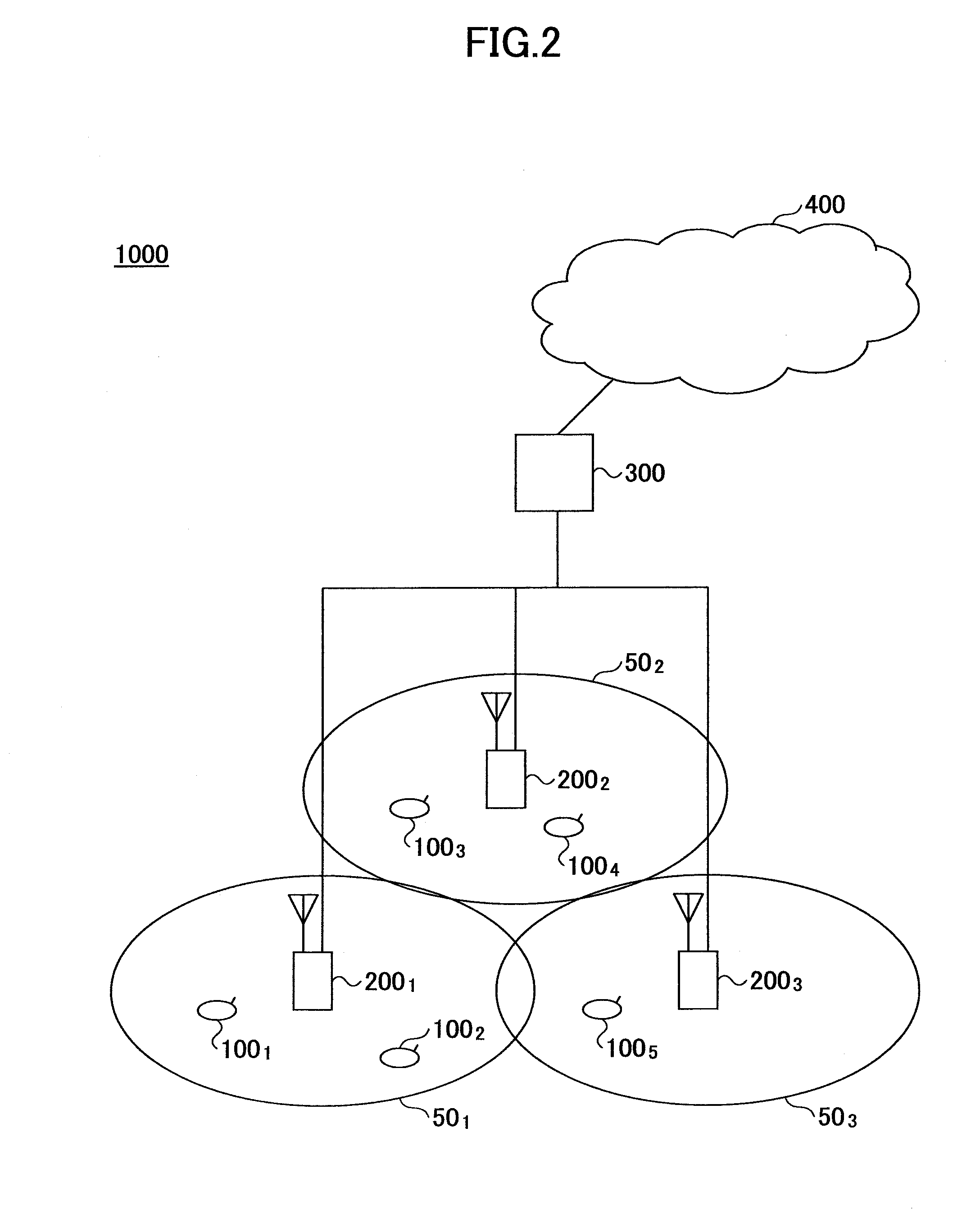
[0055]A radio communication system 1000 including user devices and base stations according to an embodiment of the present invention i...


PUM


Abstract

A base station communicates with a user device transmitting an uplink signal based on a single-carrier transmission scheme. The base station includes a frequency hopping determining unit configured to determine whether to apply frequency hopping to the user device based on radio-wave propagation information from the user device and a traffic type of data to be transmitted by the user device; a scheduler configured to allocate frequencies to the user device based on uplink channel reception conditions of the user device; and a reporting unit configured to report allocation information indicating resource units allocated by the scheduler to the user device. When the frequency hopping determining unit determines to apply the frequency hopping to the user device, the scheduler allocates, to the user device, resource units with different frequency bands in different slots.

Description

TECHNICAL FIELD[0001]The present invention generally relates to a radio communication system. More particularly, the present invention relates to a base station.BACKGROUND ART[0002]A successor communication system to W-CDMA and HSDPA, i.e., Long Term Evolution (LTE), is currently being discussed by 3GPP, a standardization group for W-CDMA. In LTE, orthogonal frequency division multiplexing (OFDM) is to be used as a downlink radio access method and single-carrier frequency division multiple access (SC-FDMA) is to be used as an uplink radio access method (see, for example, 3GPP TR 25.814 (V7.0.0), “Physical Layer Aspects for Evolved UTRA,” June 2006).[0003]In OFDM, a frequency band is divided into multiple narrow frequency bands (subcarriers) and data are transmitted on the subcarriers. The subcarriers are densely arranged along the frequency axis such that they partly overlap each other but do not interfere with each other. This method enables high-speed transmission and improves fre...

Claims


Application Information

Patent Timeline
IPC IPC(8): H04W72/04H04B1/713H04J11/00H04L27/01H04W16/02H04W72/08
CPCH04B1/713H04L1/0001H04L1/0025H04L5/0007H04W72/04H04L5/0037H04L5/0046H04L5/006H04L5/0094H04L5/0012
Inventor MIKI, NOBUHIKOKISHIYAMA, YOSHIHISAHIGUCHI, KENICHISAWAHASHI, MAMORU
Owner NTT DOCOMO INC
Learn More