Method and apparatus for pilot signal transmission

a pilot signal and transmission method technology, applied in the direction of electrical apparatus, transmission path sub-channel allocation, wireless commuication services, etc., can solve the problems of difficult to realize difficult to achieve high-performance related art pilot patterns, etc., to improve the efficiency of wireless communication systems, mitigate interference, and mitigate interference among sectors or cells

Inactive Publication Date: 2011-02-03
POS DATA CO LTD
View PDF9 Cites 42 Cited by
  • Summary
  • Abstract
  • Description
  • Claims
  • Application Information

AI Technical Summary

Benefits of technology

According to the present invention, the method and apparatus for pilot signal transmission according to the present invention has the following advantages.
Since the pilot pattern is differently uses by each sector or cell, it is possible to mitigate interference among the sectors or cells.
The mitigation of interference among the sectors or cells can improve the efficiency of wireless communication system.
When boosting the pilots, the channel estimation can be realized with the high reliability for every pilot.
Also, if the present invention is applied to the wireless communication system supporting MIMO, the pilot position is uniformly distributed per each antenna, thereby resulting in the improved channel estimation performance.
Also, the mitigation of interference among the sectors or cells and accuracy in estimation of carrier offset and channel estimation can be realized owing to the proposed pilot pattern which can reduce the pilot number per each symbol.

Problems solved by technology

However, if the proposed pilot patterns for a downlink sub-frame are applied under a multi-cell environment, every cell or sector uses the same pilot pattern so that it has a disadvantage of interference among the cells or sectors.
Also, when boosting the pilots, it is difficult for the related art pilot pattern to realize high performance for every pilot.
Thus, it has a problem that SINR (Signal to Interference Noise Ratio) of pilot symbols can not be improved by data symbols.
Also, in case of the related art pilot pattern for MIMO system, since the pilots for a specific antenna are not uniformly distributed in one bin, it is difficult to realize an optimized channel estimation performance.
In the meantime, in case of a related art pilot pattern for an uplink sub-frame, proposed for IEE 802.16m, since it is boosted by the pilot number per symbol, power is wasted due to the pilot.
Furthermore, the plurality of pilots are not positioned at the same sub-carrier, it may cause a problem of complexity in CFO (Carrier Frequency Offset) computation.
This problem becomes more serious when performing SM (Spatial Multiplexing).
Especially, in considering that the pilot is boosted for improvement of the channel estimation performance, if the pilots collide with one another, it has a problem that interference is bigger than data.

Method used


Image

  • Method and apparatus for pilot signal transmission
  • Method and apparatus for pilot signal transmission
  • Method and apparatus for pilot signal transmission

Examples


first embodiment

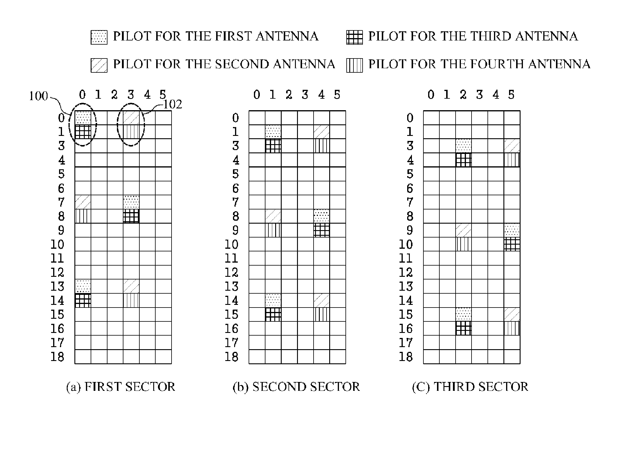
FIG. 8 illustrates a pilot pattern in the resource block of the uplink sub-frame for each sector according to the present invention.

First, FIG. 8(a) explains a rule for generating different types of pilot patterns by shifting the basic pilot pattern. In FIG. 8(a), various forms such as a circle, a triangle, a quadrangle, and a pentagon are provided to differentiate each pilot set. Each pilot set is comprised of a pilot for a first antenna or first stream, and a pilot for a second antenna or second stream. Also, the number written in each form expressing each pilot set, for example, “0”, “1”, “2”, “3”, “4”, and “5”, indicates the position-shift order of the pilot sets.

In more detail, a first pilot set 500 positioned at the 0th OFDMA symbol is shifted from the sub-carrier indexes 0 and 1 to the sub-carrier indexes 4 and 5, and then is again shifted to the sub-carrier indexes 2 and 3.

Also, a second pilot set 502 positioned at the OFDMA symbol index 1 is shifted from the sub-carrier ind...

second embodiment

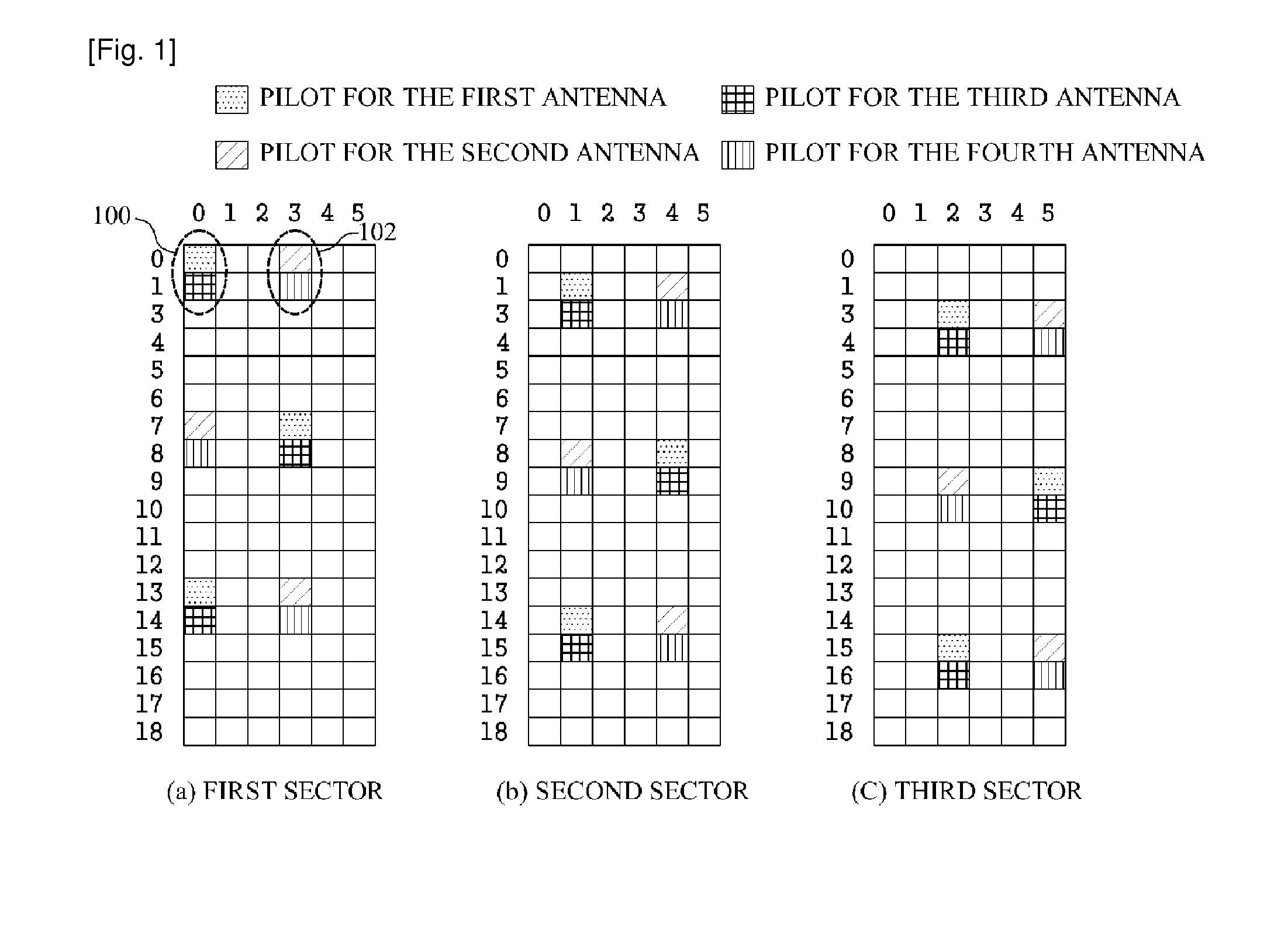
FIG. 9 illustrates a pilot pattern in the resource block of the uplink sub-frame for each sector according to the present invention.

First, FIG. 9(a) explains a rule for generating different types of pilot patterns by shifting the basic pilot pattern. In FIG. 9(a), various forms such as a circle, a triangle, a quadrangle, and a pentagon are provided to differentiate each pilot set. Each pilot set is comprised of a pilot for a first antenna or first stream, and a pilot for a second antenna or second stream. Also, the number written in each form expressing each pilot set, for example, “0”, “1”, “2”, “3”, “4”, and “5”, indicates the position-shift order of the pilot sets.

In more detail, a first pilot set 600 positioned at the OFDMA symbol index 0 is shifted from the sub-carrier indexes 0 and 1 to the sub-carrier indexes 4 and 5, and then is again shifted to the sub-carrier indexes 2 and 3.

Also, a second pilot set 602 positioned at the OFDMA symbol index 1 is shifted from the sub-carrier...

third embodiment

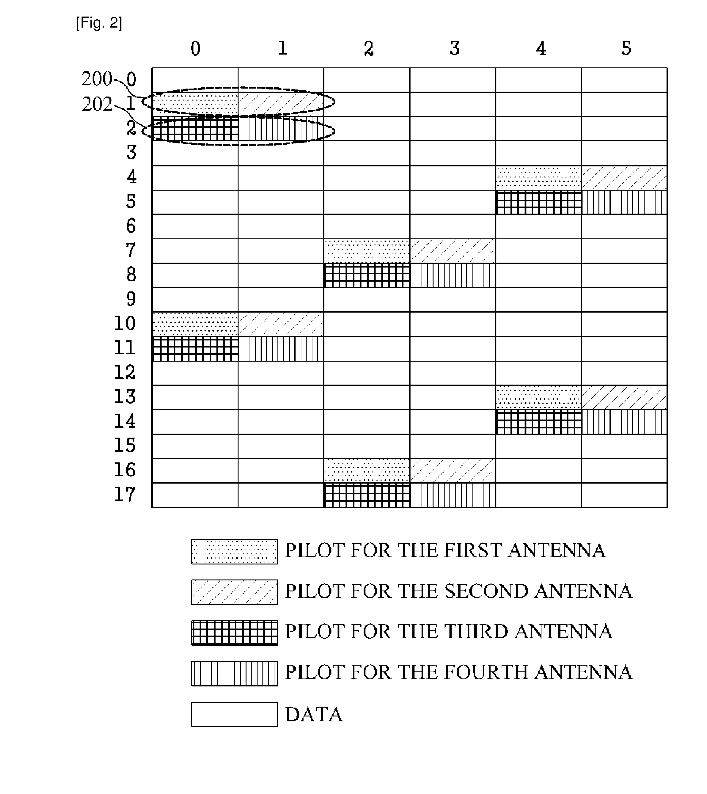
FIG. 10 illustrates a pilot pattern in the resource block of the uplink sub-frame for each sector according to the present invention.

First, FIG. 10(a) explains a rule for generating different types of pilot patterns by shifting the basic pilot pattern. In FIG. 10(a), various forms such as a circle, a triangle, a quadrangle, and a pentagon are provided to differentiate each pilot set. Each pilot set is comprised of a pilot for a first antenna or first stream, and a pilot for a second antenna or second stream. Also, the number written in each form expressing each pilot set, for example, “0”, “1”, “2”, “3”, “4”, and “5”, indicates the position-shift order of the pilot sets.

In more detail, a first pilot set 700 positioned at the OFDMA symbol index 0 is shifted from the sub-carrier indexes 0 and 1 to the sub-carrier indexes 4 and 5 at the OFDMA symbol index 4, and then is again shifted to the sub-carrier indexes 0 and 1 at the OFDMA symbol index 5.

Also, a second pilot set 702 positioned ...


PUM


Abstract

A method and apparatus for pilot signal transmission is disclosed, which is capable of improving efficiency in a wireless communication system, the method comprising transmitting an uplink transmission frame for a first sector or cell by a mobile station through the use of basic pilot pattern in a resource block and transmitting an uplink transmission frame for a second sector or cell by the mobile station through the use of shift pilot pattern which is not overlapped with the basic pilot pattern in the resource block.

Description

TECHNICAL FIELDThe present invention relates to a wireless communication system, and more particularly, to a method for a pilot signal transmission in a wireless communication system.BACKGROUND ARTIEEE (Institute of Electrical and Electronics Engineers) 802 Committee plans on developing a technology standard of IEEE 802.16m, wherein IEEE 802.16m, which is ahead of a current mobile WiMAX, is highly regarded as a next-generation technology of Wibro / Mobile WiMAX. IEEE 802.16m aims at realizing data-transmission amount of 100 Mbps under a mobile state, and data-transmission amount of 1 Gbps under an immobile state.Under a wireless communication system based on IEEE 802.16m, in the same way as related art IEEE 802.16e, a mobile station or base station has to perform a channel estimation so as to restore information data transmitted from the base station or mobile station. This channel estimation is performed using a pilot. The pilot is a signal component which corresponds to a base for e...

Claims


Application Information

Patent Timeline
Patent Type & Authority Applications(United States)
IPC IPC(8): H04W74/02
CPCH04L5/0048H04W72/044H04W48/08H04L5/005
Inventor LI, JIANJUNYUN, JUNG NAMLI, ZHENGZILEE, DONG JUNKIM, JAE HYEONG
Owner POS DATA CO LTD
Why Eureka
Try Eureka