Spatial mapping of an OFDM signal to reduce attenuation from an individual transmit antenna in a MIMO transmitter

a technology of mimo transmitter and transmit antenna, applied in the direction of digital transmission, error prevention, transmission path sub-channel allocation, etc., can solve the problem of reducing the attenuation of the stream from one or more of the antennas, unable to recover the packets from other transmit antennas, and unable to solve the problem of conventional spatial mapping techniques

Active Publication Date: 2011-02-03
GOOGLE TECH HLDG LLC
View PDF4 Cites 56 Cited by
  • Summary
  • Abstract
  • Description
  • Claims
  • Application Information

AI Technical Summary

Problems solved by technology

Problems can arise with conventional spatial mapping techniques because each transmit antenna is provided with a separate, fixed one of the streams.
For instance, if the stream transmitted from one of the antennas is sufficiently attenuated at the receiver so that packets in that stream are lost, there is no opportunity for the receiver to recover those packets from other transmit antennas.
This situation may occur when the receiver, situated in a computer, personal digital assistant (PDA), router, base station, set top box, cellular telephone or the like, is subject to interf...

Method used


Image

  • Spatial mapping of an OFDM signal to reduce attenuation from an individual transmit antenna in a MIMO transmitter
  • Spatial mapping of an OFDM signal to reduce attenuation from an individual transmit antenna in a MIMO transmitter
  • Spatial mapping of an OFDM signal to reduce attenuation from an individual transmit antenna in a MIMO transmitter

Examples


Embodiment Construction

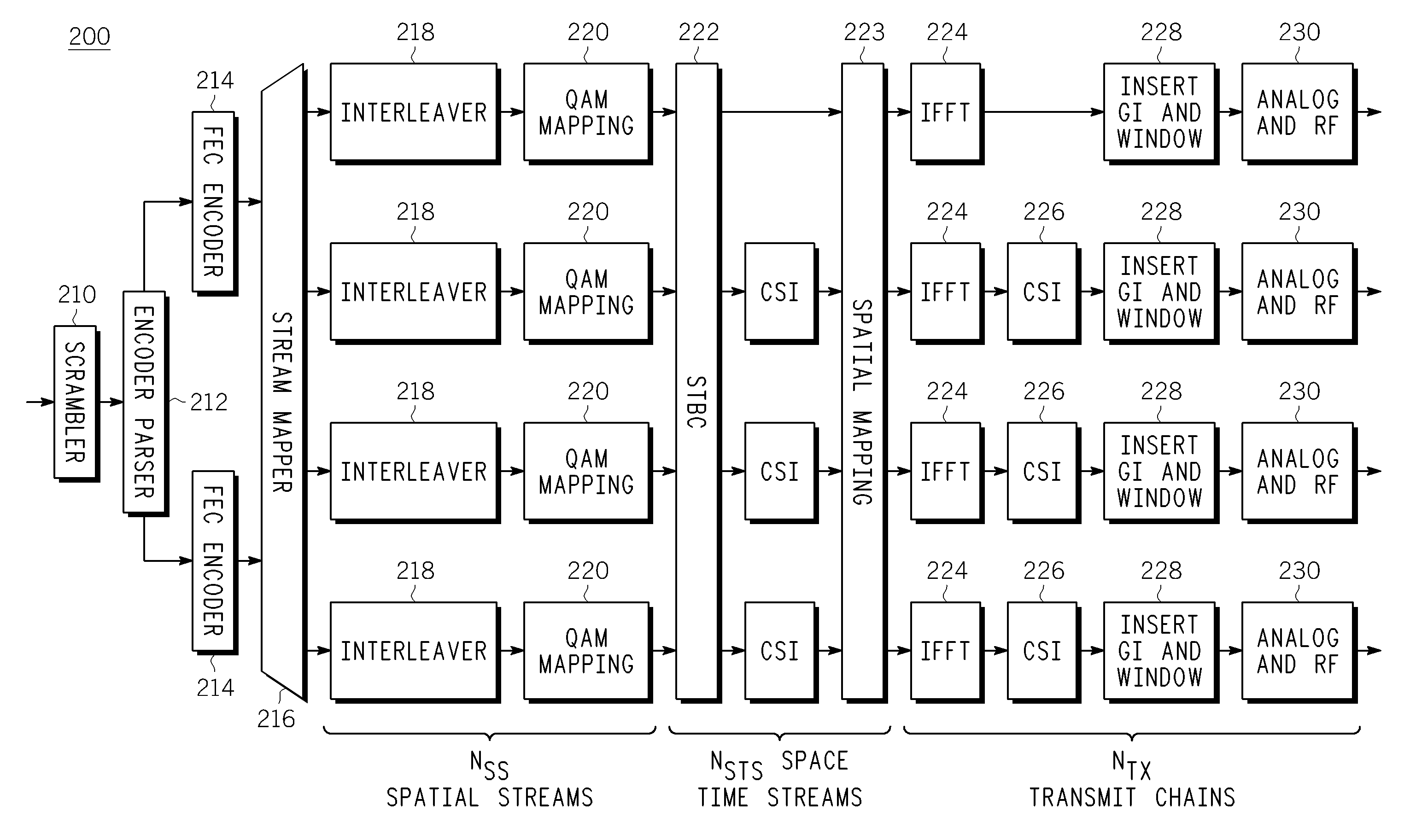
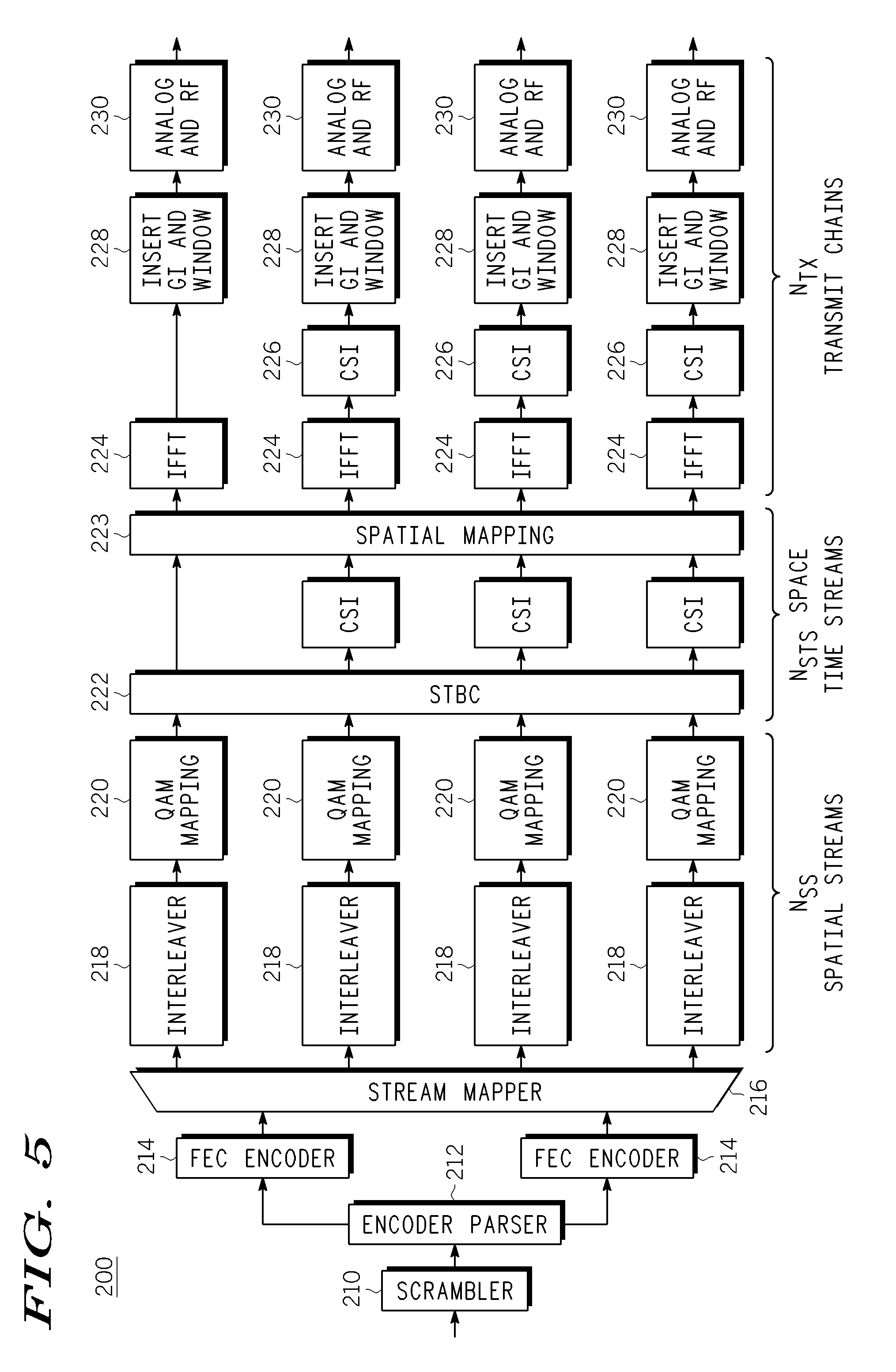
[0029]As detailed below, particular multiple antenna transmission techniques are provided for overcoming degradations to a multicarrier modulated signal being received from one or more individual antennas in a Multiple-Input-Multiple-Output (MIMO) transmitter. These multiple antenna transmission techniques advantageously facilitate the acquisition of the signal without requiring any changes in the design or operation of the MIMO receiver.

[0030]The techniques described herein can be employed on a variety of different communication methods and devices utilizing a multicarrier modulation scheme such as Orthogonal Frequency Division Multiplexing (OFDM). In general, OFDM is a block-oriented modulation scheme that maps a number of data constellation points onto a number of orthogonal carriers separated in frequency by BW / N, where BW is the bandwidth of the OFDM symbol and N is the number of tones in the OFDM symbol. OFDM is a technique by which data is transmitted at a high rate by modu...


PUM


Abstract

A method is provided for transmitting a digital signal. The method includes generating a plurality of spatial streams from a digital signal and transforming the spatial streams into a plurality of space-time streams. Each of the space-time streams are cycled in the frequency domain among each of a plurality of transmit antennas. The space-time streams are wirelessly transmitted from the plurality of transmit antennas.

Description

FIELD OF THE INVENTION[0001]The invention relates generally to multicarrier modulation techniques, and more particularly to a spatial mapping operation for OFDM signals employed in an IEEE 802.11n communication system.BACKGROUND OF THE INVENTION[0002]In recent years, wireless data communication in domestic and enterprise environments have become increasingly commonplace and an increasing number of wireless communication systems have been designed and deployed. In particular, the use of wireless networking has become prevalent and wireless network standards such as IEEE 801.11a and IEEE 801.11 g have become commonplace.[0003]The requirement for increasing data rates, communication capacity and quality of services has led to continued research and new techniques and standards being developed for wireless networking. One such standard is the IEEE 801.11n standard which is currently under development. IEEE 801.11n is expected to operate in the 2.4 GHz or 5 GHz frequency spectrum and pro...

Claims


Application Information

Patent Timeline
IPC IPC(8): H04L27/36H04L27/00
CPCH04B7/0671H04L1/0071H04L5/003H04L1/0625H04L5/0023H04L1/0618H04B7/0413H04L27/2627
Inventor ROUQUETTE-LEVEIL, STEPHANIEDE COURVILLE, MARC BERNARD
Owner GOOGLE TECH HLDG LLC
Why Eureka
Try Eureka