Multi-stage inducer for centrifugal pumps

Inactive Publication Date: 2011-02-03
ELLIOTT CO
View PDF38 Cites 3 Cited by
  • Summary
  • Abstract
  • Description
  • Claims
  • Application Information

AI Technical Summary

Problems solved by technology

A common problem with spiral inducers used within centrifugal pumps and similar devices is that the fluid in the tank in which the centrifugal pump is installed will begin to rotate in the same direction as, and along with, the inducer blades.
When this occurs, the fluid does not move up through the inducer as efficiently.
This phenomenon can also result in a change in pressure near the inlet of the inducer and increase the amount of net positive suction head (NPSH) required to make the pump continue to work efficiently or properly.
In addition, cavitation causes noise, vibration,

Method used


Image

  • Multi-stage inducer for centrifugal pumps
  • Multi-stage inducer for centrifugal pumps
  • Multi-stage inducer for centrifugal pumps

Examples


Embodiment Construction

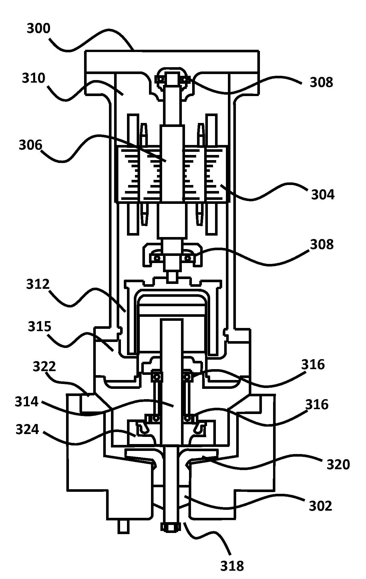
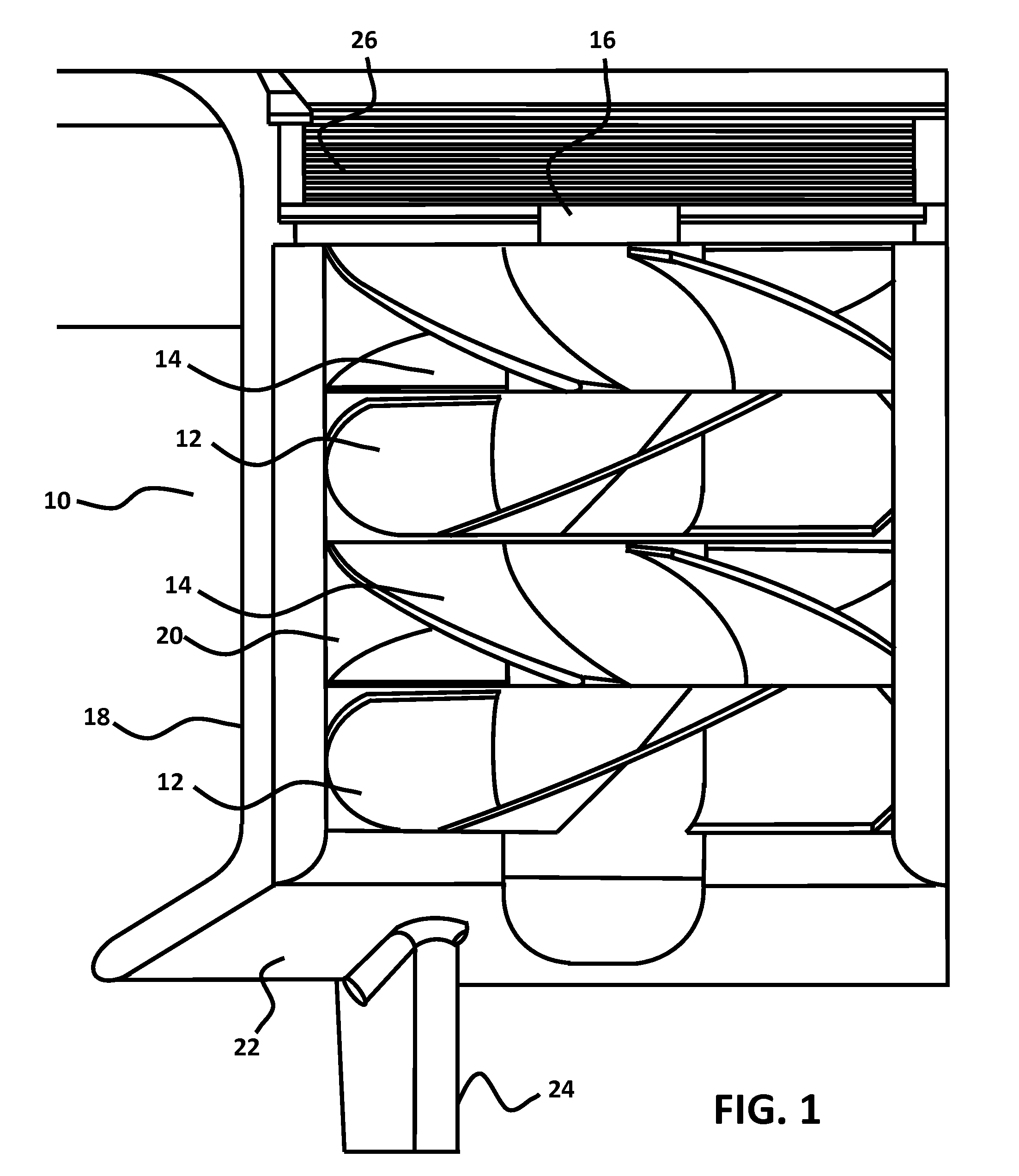
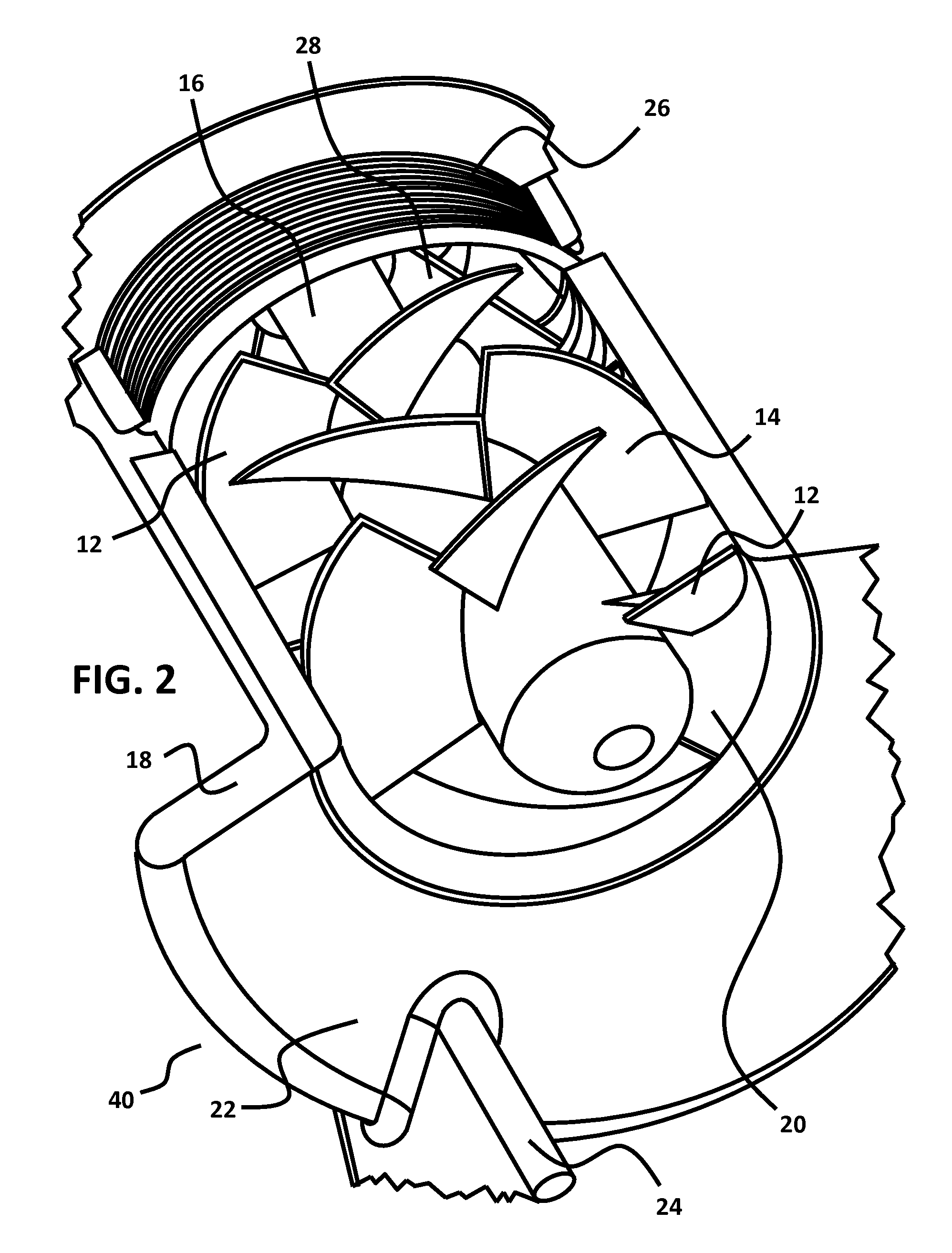
[0017]An embodiment is directed to inducers, and more particularly to an inducer that incorporates sets of rotating helical inducer vanes and sets of non-rotating helical inducer vanes. A first set of rotating vanes move the fluid up along the vanes. The sets of helical vanes are set in alternating stages, with a rotating inducer vane stage followed by a non-rotating inducer vane stage, and so on. The number of stages used before the fluid leaves the inducer and enters the impeller, or some other structure, can be varied depending upon the fluid and the process conditions, such as the structure size, but should include at least two sets. Embodiments of the multi-state inducer can be positioned at the inlet of a cryogenic centrifugal pump. Alternative embodiments can be positioned at the inlet of a cryogenic centrifugal pump with a vertical rotational axis and a thrust equalizing mechanism device.

[0018]The fluid gains rotational momentum as a result of passing through the rotating va...


PUM


Abstract

An inducer assembly comprising at least two sets of rotating and non-rotating helical inducer vanes. As the fluid enters the inducer, the fluid moves up through a first set of rotating vanes, and gains rotational momentum. The fluid then enters a second set of non-rotating vanes that use the rotational momentum of the fluid to progress the fluid forward while removing the rotation and consequently decreasing the net positive suction head required. The inducer is positioned at the inlet of a cryogenic centrifugal pump. Embodiments of the cryogenic centrifugal pump use a vertical rotational axis and include a thrust equalizing mechanism device to balance hydraulic thrust.

Description

CROSS-REFERENCES TO RELATED APPLICATIONS[0001]This application claims priority from provisional patent application Ser. No. 61 / 273,377, filed Aug. 3, 2009, which is hereby incorporated herein by reference in its entirety to be considered part of this specification.BRIEF DESCRIPTION OF THE INVENTION[0002]An inducer comprising at least two sets of rotating and non-rotating helical inducer vanes. As the fluid enters the inducer, the fluid moves up through a first set of rotating vanes, and gains rotational momentum. The fluid then enters a second set of non-rotating vanes that use the rotational momentum of the fluid to progress the fluid forward while removing the rotation, which consequently decreases the net positive suction head required. The inducer is positioned at the inlet of a cryogenic centrifugal pump. Embodiments of the cryogenic centrifugal pump use a vertical rotational axis and include a thrust equalizing mechanism device to balance hydraulic thrust.STATEMENTS AS TO THE ...

Claims


Application Information

Patent Timeline
IPC IPC(8): F04D29/22
CPCF04D29/181F04D29/448F04D29/2277F04D29/185F04D7/00
Inventor FINLEY, CHRISTOPHER D.
Owner ELLIOTT CO
Why Eureka
Try Eureka