Eureka AIR delivers breakthrough ideas for toughest innovation challenges, trusted by R&D personnel around the world.

Fixation plate screw retention

Inactive Publication Date: 2011-02-03
GLAZER PAUL ANDREW
View PDF21 Cites 18 Cited by
  • Summary
  • Abstract
  • Description
  • Claims
  • Application Information

AI Technical Summary

Benefits of technology

[0011]In certain embodiments, the shaft of the screw includes a circumferential channel which is configured to receive the retainer. The channel can include a bottom surface which is formed at an oblique angle with respect to the longitudinal axis of the screw, wherein the channel is configured to receive the retainer. The retainer can have an inner peripheral surface which is adapted to mate with the bottom surface of the channel when the retainer is radially compressed into the channel. At least one corner of the retainer can be rounded to facilitate engagement of the retainer in the channel. The bottom surface of the channel can be at an angle of about eight degrees to about fifteen degrees with respect to the longitudinal axis of the screw, wherein the channel is configured to receive the retainer. It is also contemplated that the bottom surface of the channel can be at an angle of about twelve degrees, or any other suitable angle, with respect to the longitudinal axis of the screw.

Problems solved by technology

While the procedure of implanting a bone fixation plate carries its own potential for complications, an added risk of complication is in the tendency of fixation screws to back out or loosen with respect to the remaining implant components.
The loosening of the screws can lead to failure of the device.
In the case of cervical spine fixation, for example, a loose screw could penetrate the esophagus causing infection.
Such a secondary locking screw inherently increases the complexity and cost of the device while further increasing the implantation time.
Also, these secondary locking screws themselves can loosen and back out of the plate over time.

Method used


Image

  • Fixation plate screw retention
  • Fixation plate screw retention
  • Fixation plate screw retention

Examples


Embodiment Construction

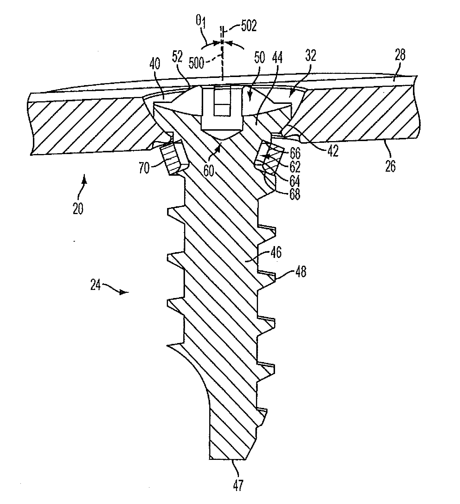
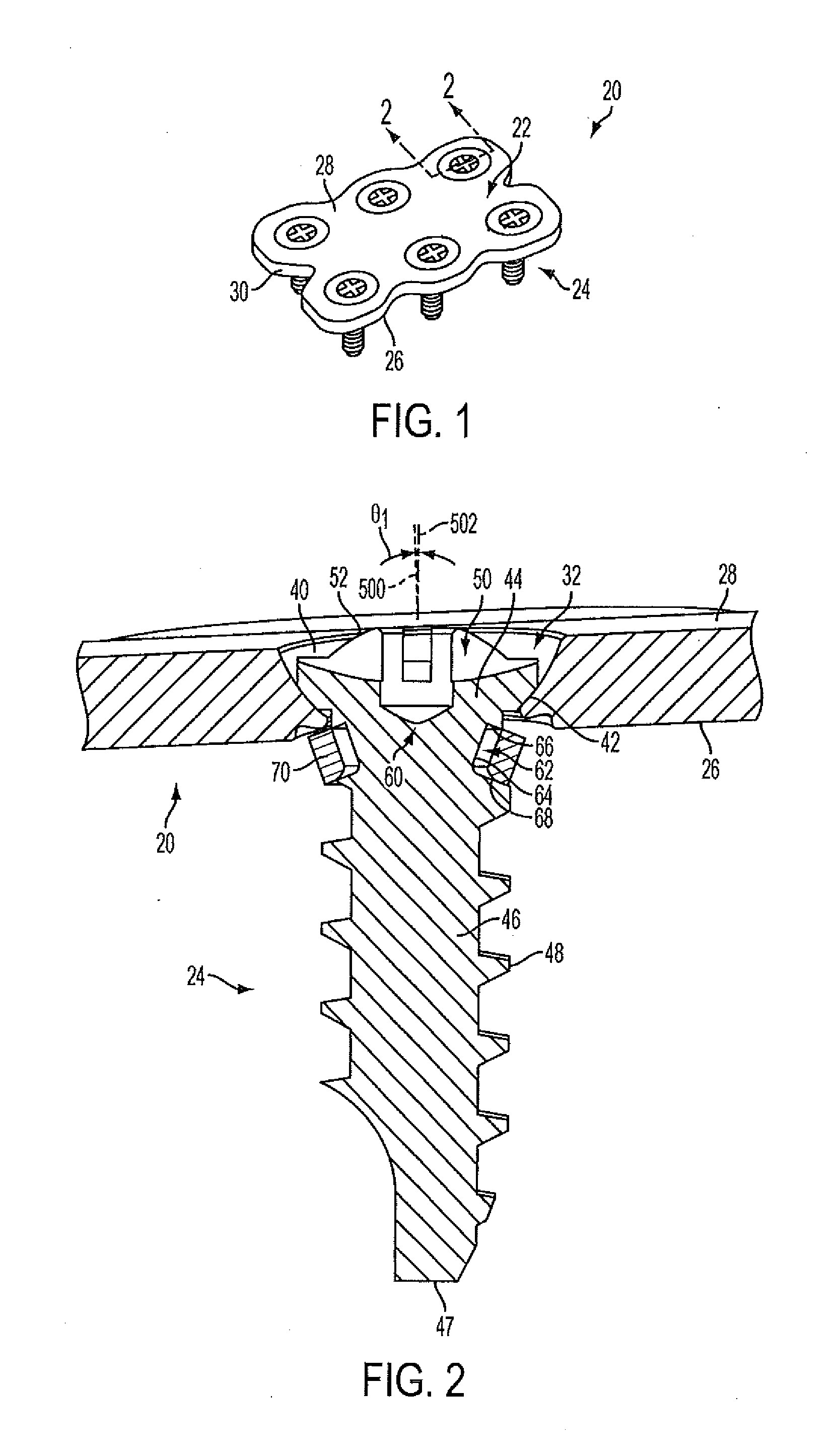
[0036]Reference will now be made to the drawings wherein like reference numerals identify similar structural features or aspects of the subject invention. For purposes of explanation and illustration, and not limitation, a perspective view of an exemplary embodiment of a fixation plate system in accordance with the invention is shown in FIG. 1 and is designated generally by reference character 20. Other embodiments of fixation plate systems in accordance with the invention, or aspects thereof, are provided in FIGS. 2-14C, as will be described. The systems of the invention can be used to provide a fixation plate screw locking system that allows for improved prevention of fixation screws from backing out while having fixation screws that can still be removed from the plate if necessary, for example.

[0037]FIG. 1 shows a bone fixation plate assembly 20 including a plate 22 and a plurality of screws 24. The exemplary plate is formed as a unitary single metal piece having a second face 26...


PUM


Abstract

A screw fixation system includes a plate having opposed first and second surfaces, and a hole defined in the plate which extends between the first and second surface. A screw is included having a head and a shaft extending from the head and defining a longitudinal axis for the screw, the shaft of the screw being configured and adapted to be inserted into the hole. A retainer is circumferentially positioned around the shaft of the screw and proximate to the screw head. The retainer is configured to engage with the plate proximate the hole when the shaft of the screw has been inserted into the hole so as to resist removal of the screw from the hole and to allow removal of the screw from the hole when a preset torque is applied to the screw.

Description

CROSS-REFERENCE TO RELATED APPLICATIONS[0001]This application claims the benefit of priority to U.S. Provisional Application No. 61 / 229,525, filed Jul. 29, 2009, which is hereby incorporated by reference in its entirety.BACKGROUND OF THE INVENTION[0002]1. Field of the Invention[0003]The present invention relates to fixation plates. More particularly, the invention relates to controlling the backing out of screws from such fixation plates.[0004]2. Description of Related Art[0005]A wide variety of bone fixation plates exist. An exemplary plate carries a number of screws, each extending through an associated aperture in the plate and attached to bone. In the art of orthopedic fixation, it is now common for surgeons to utilize fixation plates for the treatment of spinal disorders which can include spinal anomalies, spinal injuries, disc conditions, and bone conditions.[0006]While the procedure of implanting a bone fixation plate carries its own potential for complications, an added risk...

Claims


Application Information

Patent Timeline
IPC IPC(8): A61B17/80
CPCA61B17/8052A61B17/8047
Inventor CRAINICH, LAWRENCE
Owner GLAZER PAUL ANDREW
Why Eureka
Eureka Blog
Learn More