Hip prosthesis

Inactive Publication Date: 2011-02-03
CARTILLIER JEAN CLAUDE +11
View PDF16 Cites 5 Cited by
  • Summary
  • Abstract
  • Description
  • Claims
  • Application Information

AI Technical Summary

Benefits of technology

[0017]According to a characteristic of the invention, one of the edges of the slot extends into the continuity of the inner surface of the medullar part. These provisions allow a guide of the osteotomes along the slot, and preventing the latter to abut against the inner surface of the medullar part and against the edge of the calcar.
[0018]Conveniently, the prosthesis comprises a removable shutter arranged to shut the slot. Such a shutter is designed to

Problems solved by technology

However, such a collar support has the disadvantage of causing a peak of stresses in the calcar, which may generate a bone degradation of the latter.
In addition, since such a collar support covers the internal cortex of the femur an

Method used


Image

  • Hip prosthesis
  • Hip prosthesis
  • Hip prosthesis

Examples


Example

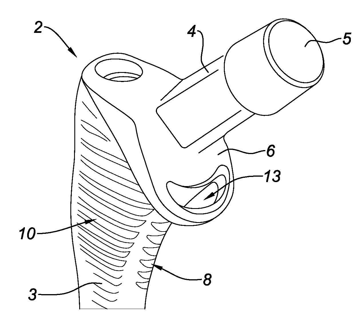
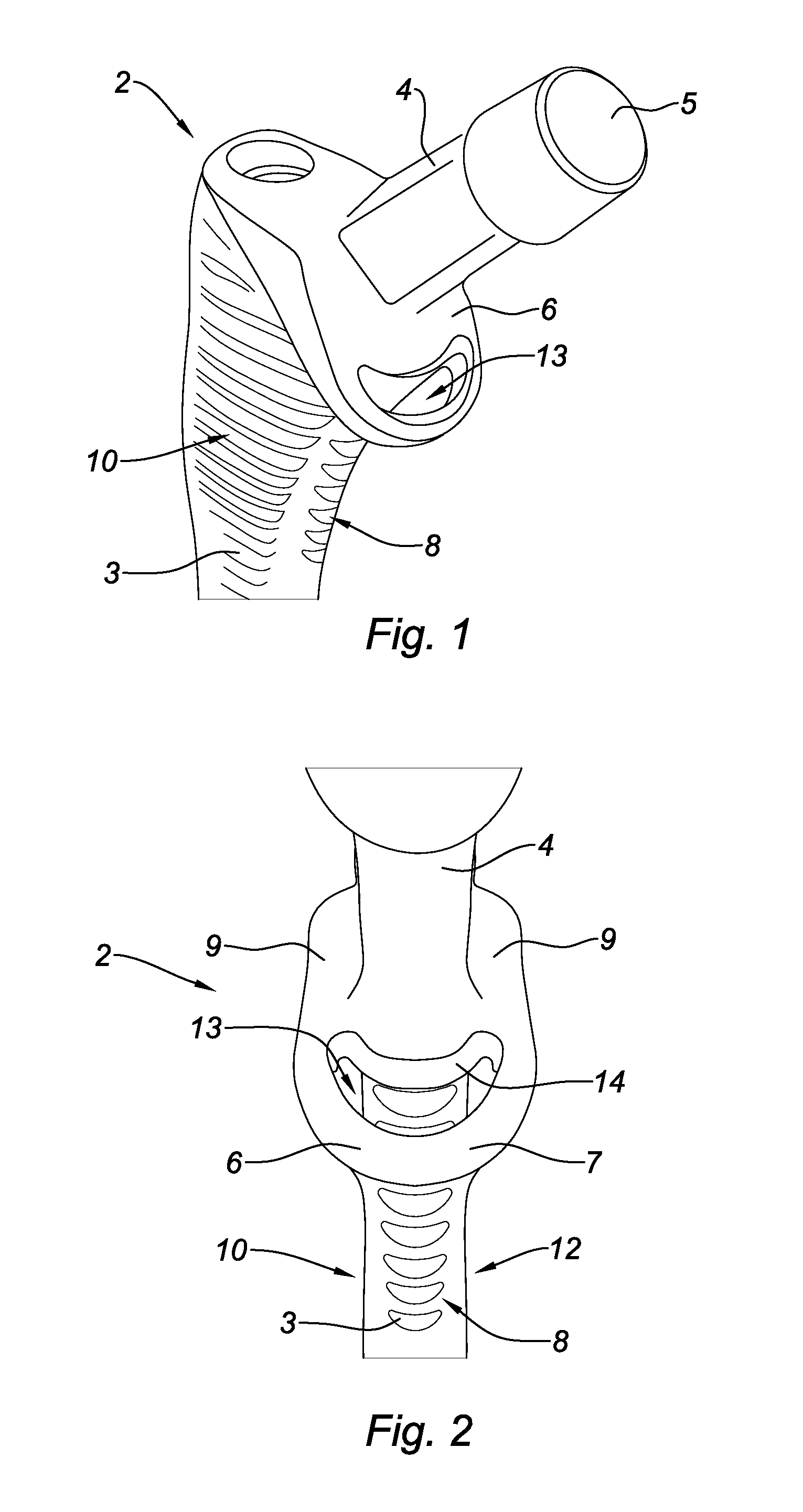
[0030]FIGS. 1 and 2 represent a hip prosthesis 2 preferably made of titanium, titanium alloy or chrome cobalt.

[0031]The hip prosthesis 2 comprises a medullar part 3 of elongated shape intended to be engaged in the medullary canal of a femur, and a part forming a prosthetic femoral neck 4 intended to project from the femur and be fitted with a prosthetic femoral head (not shown in the Figures).

[0032]The part forming the femoral neck 4 comprises a tapered proximal end 5 arranged to cooperate with a tapered cavity of complementary shape formed in the prosthetic femoral head.

[0033]The hip prosthesis 2 also comprises a collar support 6 located at the junction between the medullar part 3 and the part forming the femoral neck 4.

[0034]The support collar 6 extends substantially perpendicular to the part forming the femoral neck 4. The collar support 6 extends also substantially at an angle of about 45° in relation to the dialphyseal axis.

[0035]The support collar 6 is intended to take support...


PUM


Abstract

Hip prosthesis including a medullar part of elongated shape intended to be engaged in the medullary canal of a femur, one part forming the prosthetic femoral neck intended to project from the femur and be fitted with a prosthetic femoral head, and a support collar extending transversely to the part forming the femoral neck and intended to take support on the femoral cortex, where the support collar includes a slot.

Description

TECHNICAL FIELD[0001]This invention relates to a hip prosthesis.BACKGROUND[0002]A hip prosthesis comprises, in a known manner, an elongated shape medullar part intended to be engaged in the medullary canal of a femur, a part forming a prosthetic femoral neck intended to project from the femur and to be fitted with a prosthetic femoral head and a support collar extending transversally to the part forming the femoral neck and intended to take support on the femoral cortex, and more particularly on the spur of Meckel, also called calcar.[0003]The presence of the collar support allows on one hand to prevent a penetration of the medullar part in the medullar canal of the patient beyond a specified area, and on the other hand to improve the seat of the prosthesis.[0004]However, such a collar support has the disadvantage of causing a peak of stresses in the calcar, which may generate a bone degradation of the latter.[0005]In addition, since such a collar support covers the internal cortex ...

Claims


Application Information

Patent Timeline
IPC IPC(8): A61F2/32
CPCA61F2/30728A61F2/30734A61F2/30744A61F2/36A61F2/3609A61F2002/30571A61F2002/4619A61F2002/30677A61F2002/3068A61F2002/30729A61F2002/30779A61F2002/3643A61F2002/30617A61F2002/30772A61F2002/3631
Inventor CARTILLIER, JEAN-CLAUDEJACQUOT, LAURENTBALAY, BRUNOCHARLET, CLAUDEFESSY, MICHEL HENRISEMAY, JEAN MARCSETIEY, LOUISCHATELET, JEAN-CHRISTOPHEVIDALAIN, JEAN PIERREMACHENAUD, ALAINAIT SI SELMI, TARIKROLLIER, JEAN-CHARLES
Owner CARTILLIER JEAN CLAUDE
Why Eureka
Try Eureka