

Exhaust gas purifying device
- Summary
- Abstract
- Description
- Claims
- Application Information
AI Technical Summary
Benefits of technology
Problems solved by technology
Method used
Image

Examples
first embodiment
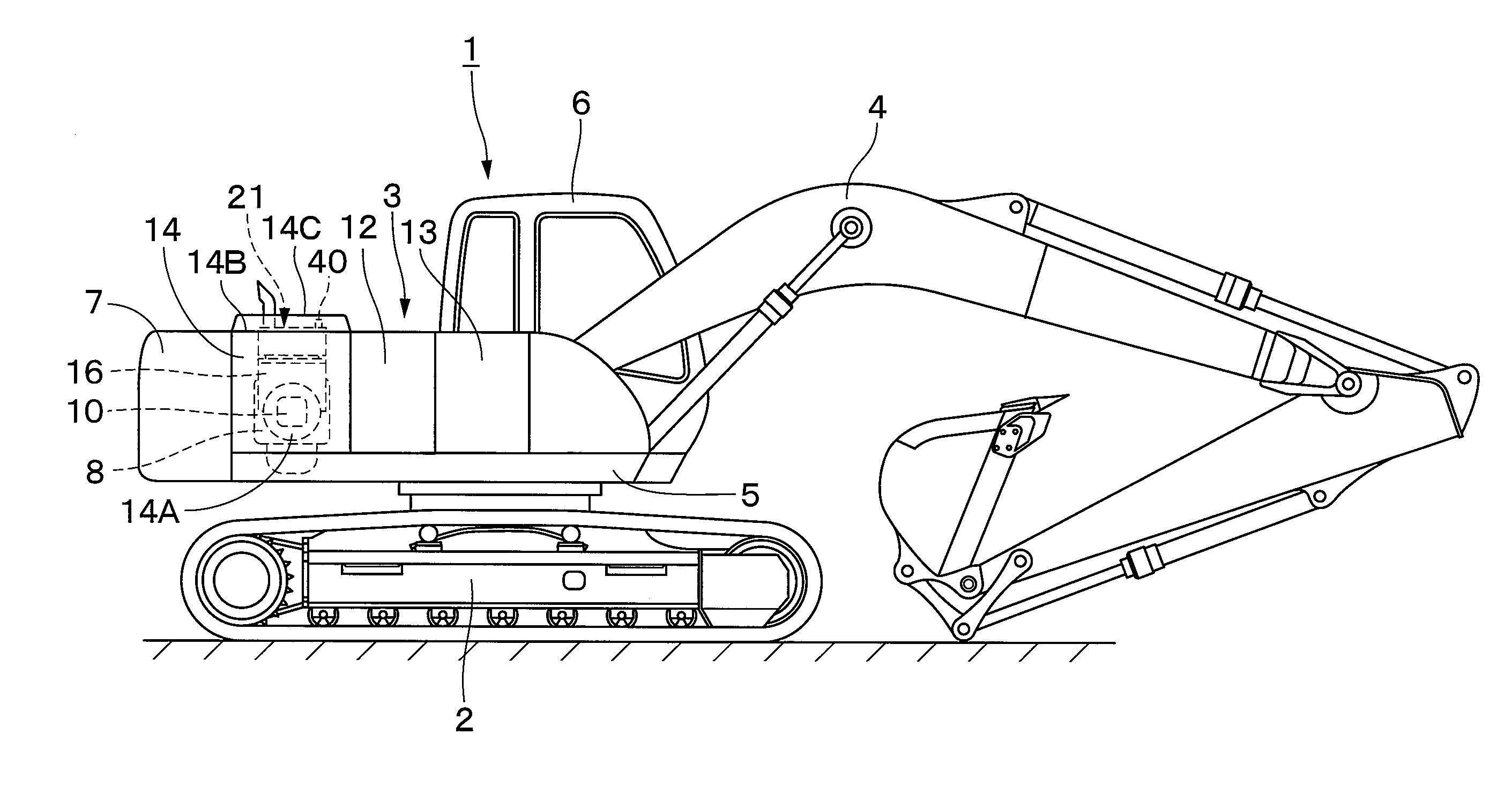
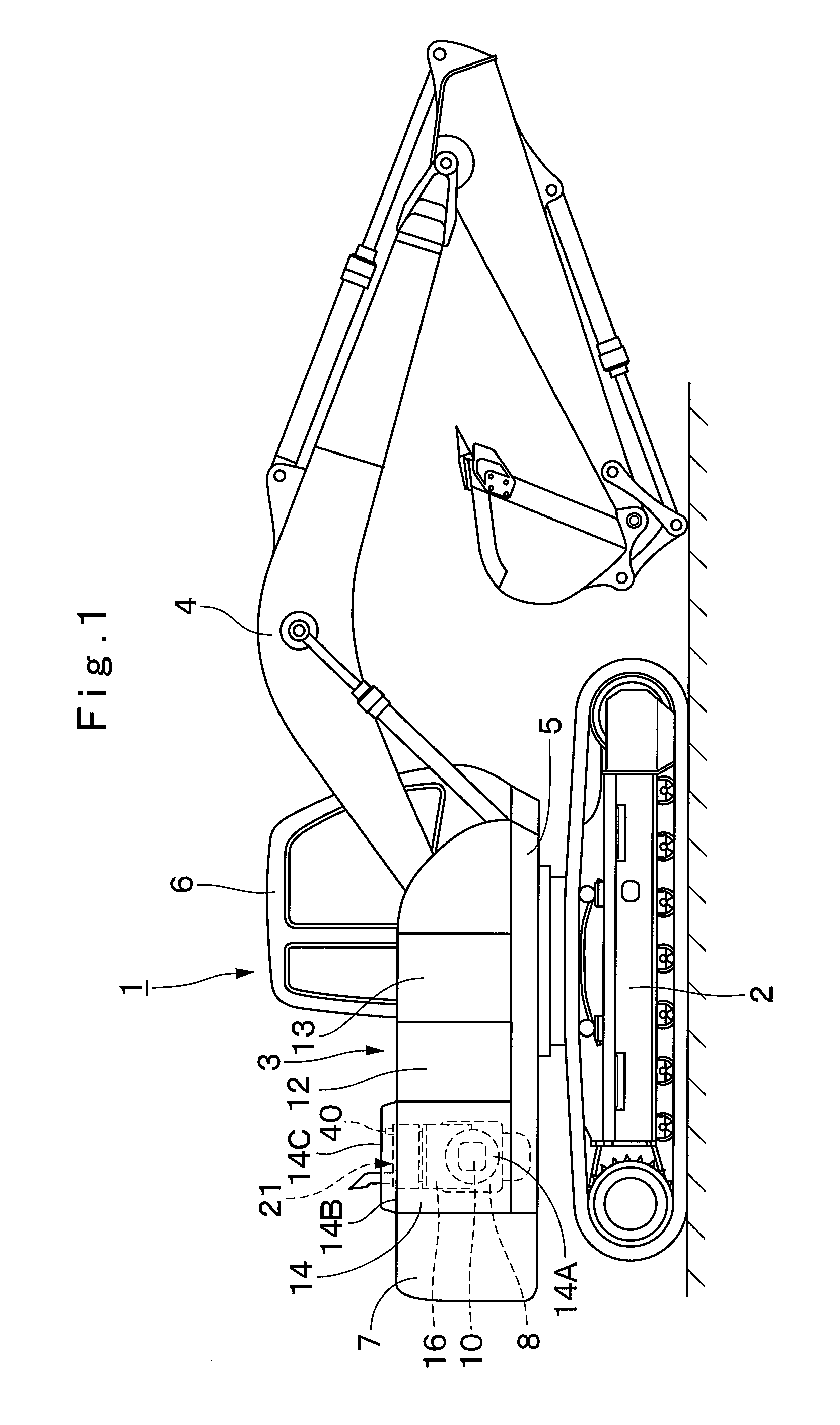
[0084]FIGS. 1 to 11 show the exhaust gas purifying device in accordance with the present invention.
[0085]In FIG. 1, designated at 1 is a crawler type hydraulic excavator as a construction machines, and the hydraulic excavator 1 is largely constituted by an automotive lower traveling structure 2, an upper revolving structure 3 which is swingably mounted on the lower traveling structure 2 and constitutes a vehicle body together with the lower traveling structure 2, and a working mechanism 4 liftably mounted on the front side of the upper revolving structure 3 to perform such as the operation of excavating earth and sand. The lower traveling structure 2 and the upper revolving structure 3 are specific examples of the vehicle body in accordance with the invention.
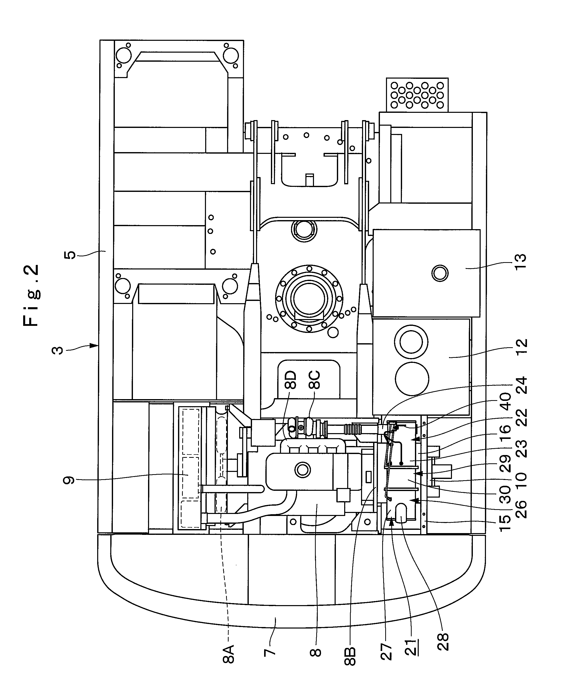
[0086]Here, a detailed description will be given of the upper revolving structure 3 for constituting the hydraulic excavator 1. Designated at 5 is a revolving frame of the upper revolving structure 3, and the revolving frame 5 ...
second embodiment
[0163]In FIG. 12, designated at 51 is an exhaust gas purifying device in accordance with a Denoted at 52 is an upstream cylinder of the exhaust gas purifying device 51, and the upstream cylinder 52 is constituted by a first cylindrical member 53 on the upstream side (front side), a second cylindrical member 54 connected to the downstream side of that first cylindrical member 53, the inlet pipe 24 provided on the first cylindrical member 53, and the oxidation catalyst 25 provided in the second cylindrical member 54.
[0164]Indicated at 53 is the first cylindrical member for making up an upstream side portion of the upstream cylinder 52, and the first cylindrical member 53 is constituted by a cylindrical portion 53A, a lid portion 53B, a flange portion 53C, support legs 53D, and the like in substantially the same way as the cylindrical member 23 in accordance with the first embodiment. Further, the inlet pipe 24 is attached to the cylindrical portion 53A of the first cylindrical member...
PUM
| Property | Measurement | Unit |
|---|---|---|
| Temperature | aaaaa | aaaaa |
Abstract
Description
Claims
Application Information