
Method and a spraying device for the repair of a sandwich plate

Active Publication Date: 2011-02-10
AIRBUS OPERATIONS GMBH
View PDF1 Cites 13 Cited by
  • Summary
  • Abstract
  • Description
  • Claims
  • Application Information

AI Technical Summary

Benefits of technology

[0008]Accordingly, an aspect of the invention is to create an improved method that enables a simple, rapid and cost-effective repair option for regions of damage in sandwich plates, in particular floor plates of aircraft, in the field, and without the necessity of removing the sandwich plate.

Problems solved by technology

In normal flight operations of a passenger aircraft the floor plates are themselves subjected to high mechanical loadings in what is often also a chemically aggressive environment.
These result in indentations (so-called “impacts”) of the upper surface layer of the floor plate, and vertical compressions of the core structure in the region of damage.
As a consequence of the compressions a further result is spalling of the impregnation of the core structure, as a result of which the latter's strength is severely impaired.
Without timely repair of the region of damage in question the latter extends ever further outwards, and can lead to deterioration of the floor plate over a large area.
Removal and replacement of the floor plate in question is as a rule not possible in the field, and moreover would also be linked with excessive costs for labour and materials.
What is disadvantageous in this procedure is that filling the honeycombs is not possible without the formation of air bubbles, where these preferentially move into the region below the upper surface layer.
However, the main disadvantage of this procedure is to be seen in the fact that in the damage location region destruction of the honeycomb-shaped core structure takes place over a large volume.
However, this method necessarily assumes the removal of the floor plate that is to be repaired.

Method used


Image

  • Method and a spraying device for the repair of a sandwich plate
  • Method and a spraying device for the repair of a sandwich plate
  • Method and a spraying device for the repair of a sandwich plate

Examples


Embodiment Construction

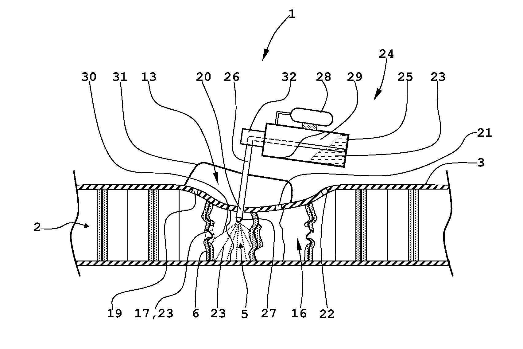
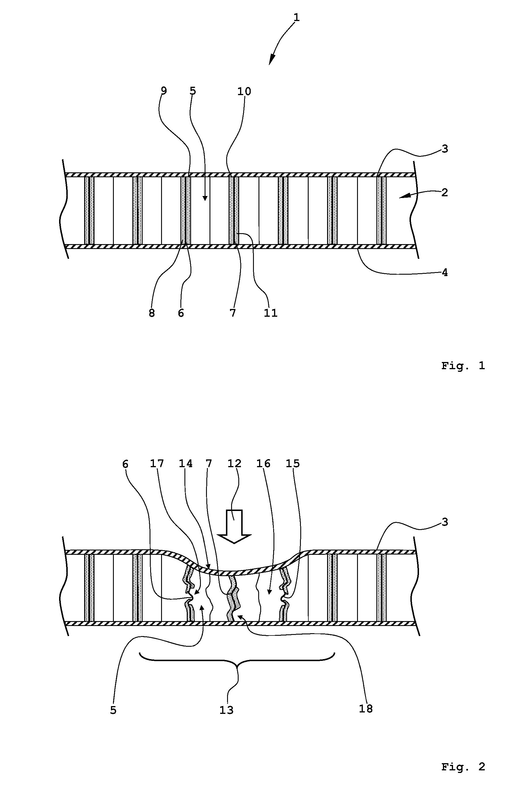
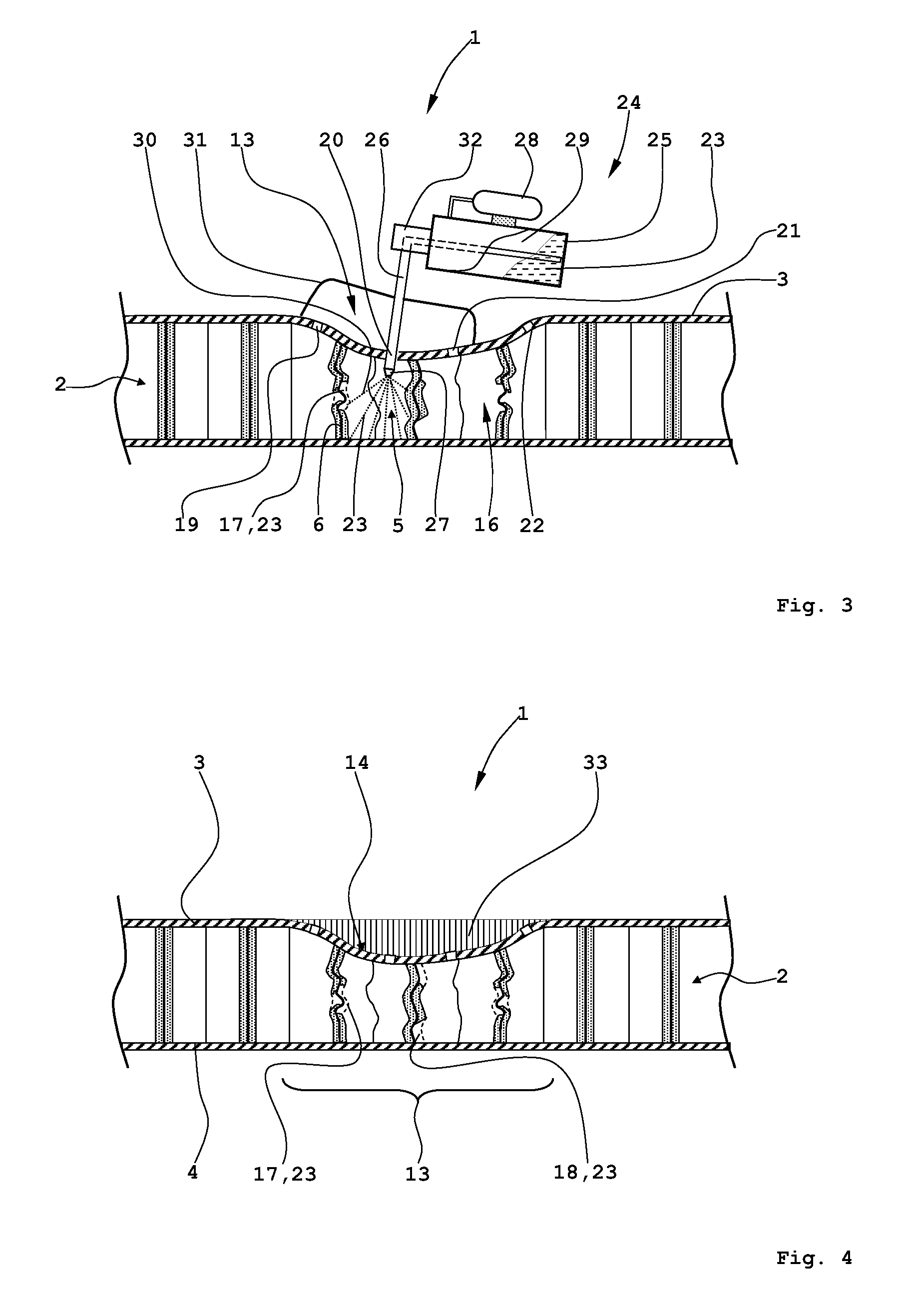
[0045]FIG. 1 shows a schematic illustration of a cross-section through a sandwich plate, which finds widespread application as a floor plate in passenger cabins or freight compartments of aircraft.

[0046]The sandwich plate 1 comprises inter alia a core structure 2, which is provided on both sides with two surface layers 3, 4. The core structure 2 itself is formed with a multiplicity of honeycomb-shaped cells, of which one cell 5 is provided with a reference number to represent all the others. Both sides of the wall surfaces 6, 7 of the cell 5, and also all other cells of the core structure 2, are formed in this example of embodiment with a polyamide paper, which is saturated, coated and / or impregnated with a phenolic resin. (so-called Nomex® paper). In the illustration of FIG. 1 a total of four phenolic resin layers 8 to 11 are present on the two sides of the wall surfaces 6, 7, where the material thickness of the phenolic resin layers 8 to 11 is graphically illustrated in a strongly...


PUM

PropertyMeasurementUnit
Thermosettingaaaaaaaaaa

Abstract

A method for the repair of a sandwich plate having a core structure, a top surface layer and a bottom surface layer and a plurality of honeycomb-shaped cells includes providing at least one penetrating drill hole in at least one of the top surface layer and the bottom surface layer above one of the plurality of honeycomb-shaped cells in a damaged region of the sandwich plate, injecting a stabilising material into the honeycomb-shaped cell, and filling the damaged region with a filler material.

Description

CROSS REFERENCE TO PRIOR APPLICATIONS[0001]Priority is claimed to German Application No. DE 10 2009 035 108.6, filed Jul. 29, 2009 and U.S. Provisional Application No. 61 / 229,288, filed Jul. 29, 2009. The entire disclosure of both documents is incorporated by reference herein.FIELD[0002]The invention concerns a method for the repair of a sandwich plate, in particular a floor plate in an aircraft, wherein the sandwich plate has a core structure, provided on both sides with surface layers, with a multiplicity of in particular honeycomb-shaped cells.BACKGROUND[0003]Sandwich plates find widespread application in aircraft construction by virtue of their extraordinarily favourable ratio between achievable rigidity and weight. For example, floor plates, which are constructed using sandwich plates with a honeycomb-shaped core structure and surface layers of carbon fibre-reinforced epoxy resins fitted on both sides of the core structure, are installed in passenger cabins or in freight compar...

Claims


Application Information

Patent Timeline
IPC IPC(8): B29C73/02B29C73/12
CPCB05B7/2472B05D7/22B29C73/025B29C73/26B32B3/12B32B5/28B32B27/02B32B27/04B32B27/12B32B27/34B32B27/38B32B43/00B32B2305/024B32B2305/028B32B2398/10B64F5/0081B29C73/02B32B5/02B32B5/22B32B5/26B32B15/20B32B2260/021B32B2260/046B32B2262/0269B32B2262/106B32B2307/50B32B2307/714B32B2307/718B32B2307/7265B32B2605/18B64F5/40
Inventor SCHOKE, BERENDDOECKER, MICHAEL
Owner AIRBUS OPERATIONS GMBH
Learn More