Cooling device
- Summary
- Abstract
- Description
- Claims
- Application Information
AI Technical Summary
Benefits of technology
Problems solved by technology
Method used
Image

Examples
first embodiment
[0072]A cooling roller and a cooling device according to embodiments of the present invention will be described in connection with an image forming device which fixes a toner on a recording paper through a heat fixing unit. However, the cooling roller and the cooling device of the present invention are not limited thereto and can be applied to any device requiring cooling of a sheet medium.
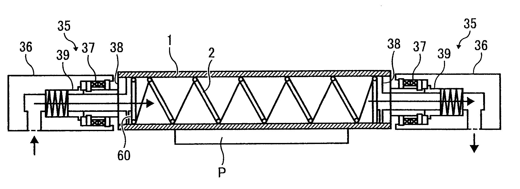
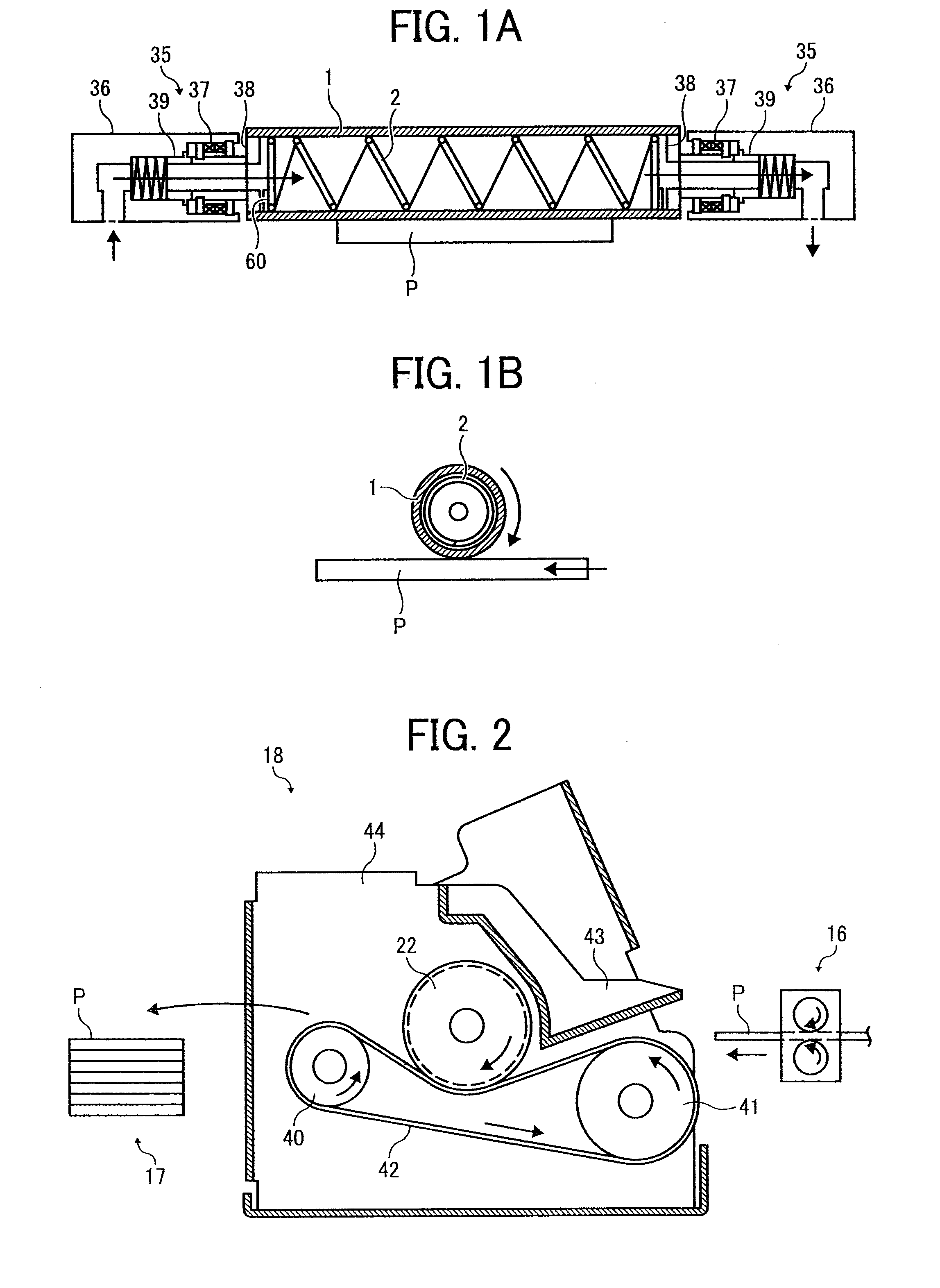
[0073]The cooling roller as a cooling unit has a tubular structure and allows the cooling liquid to flow and circulate thereinside to cool down a surface of the cooling roller. The cooling device having the cooling roller is disposed in a paper transport path directly behind a heat fixing unit and comes into contact with the paper while transporting the paper through the cooling roller, thereby removing heat from the paper to cool down the paper.
[0074]FIG. 2 is a schematic view illustrating an example of a cooling device 18 having a cooling roller 22 of the present invention which also performs a ...
example 1
[0161]The cooling roller 22 of the present invention was applied to a modified device of a color image forming device “Imagio Neo C600” made by Ricoh Co., Ltd. “Imagio Neo C600” employs a tandem-type and an indirect transfer technique illustrated in FIG. 22.
[0162]The cooling roller 22 was configured such that the coil-like member 2 having a line thickness of 0.5 [mm] and a pitch of 6 [mm] was inserted along the inner wall of the outer tube 1, made of aluminum, having an outer diameter of φ30.4 [mm] and a thickness of 1.1 [mm], and two rotary joints for a one-way flow made by Showa Giken Industrial Corporation were sealably and rotatably mounted to both ends of the cooling roller.
[0163]Two corrugated radiators (thickness 20 [mm]) that have a square shape having one side of 120 [mm] and are made of aluminum were connected in series. An axial flow fan (flow velocity 2.3 [m / s]) that has the same size as the radiator and has a square shape having one side of 120 [mm] was used as the radi...
example 2
[0165]As the cooling roller 22 of Example 2, employed was a configuration in which the outer tube 1 is made of aluminum and has an outer diameter of φ30.4 [mm] and a thickness of 1.1 [mm], the inner tube 7 is made of aluminum, the cylinder 8 is mounted in the inner tube 7, and the coil-like member 2 having a line thickness of 0.5 [mm] and a pitch of 16 [mm] is inserted along the inner wall of the outer tube 1. Further, a configuration, in which a rotary joint for a two-way flow made by Showa Corporation is sealably and rotatably mounted to a one end of the cooling roller 22, was employed. In this time, the inner tube 7 had an outer diameter of φ4 [mm], and a space between the outer tube 1 and the cylinder 8 was 1.1 [mm].
[0166]By such a configuration, color two-sided continuous printing that was performed for 75 sheets per one minute was continuously performed for four hours. In order to measure the temperature of the paper, thin thermocouples were disposed in a paper transport passa...
PUM
 Abstract
Description
Claims
Application Information
 - R&D
- Intellectual Property
- Life Sciences
- Materials
- Tech Scout
- Unparalleled Data Quality
- Higher Quality Content
- 60% Fewer Hallucinations
Browse by: Latest US Patents, China's latest patents, Technical Efficacy Thesaurus, Application Domain, Technology Topic, Popular Technical Reports.
© 2025 PatSnap. All rights reserved.Legal|Privacy policy|Modern Slavery Act Transparency Statement|Sitemap|About US| Contact US: help@patsnap.com