
Live Router Migration

a router and live router technology, applied in the field of router migration, can solve the problems of network outages caused by operator errors, network operators are unable to provide seamless service in the face of changes to the underlying network, and the cost of personnel and systems which manage the network typically exceeds the cost of the underlying nodes and links, etc., to achieve the effect of easy and rapid migration of virtual routers

Inactive Publication Date: 2011-02-10
AT&T INTPROP I L P
View PDF5 Cites 233 Cited by
  • Summary
  • Abstract
  • Description
  • Claims
  • Application Information

AI Technical Summary

Benefits of technology

[0008]It is an advantage of the present invention that live router migration may be used in situations where a physical router must undergo planned maintenance. In this case, the virtual routers are moved (in advance) to another physical router in the same Point-of-Presence (PoP). Additionally, edge routers can be moved from one location to another by virtually re-homing the links that connect to neighboring domains.

Problems solved by technology

Indeed, the cost of personnel and systems which manage a network typically exceeds the cost of the underlying nodes and links.
Additionally, most network outages are caused by operator errors, rather than equipment failures.
From routine tasks such as “planned maintenance” to the less-frequent deployment of new protocols, network operators struggle to provide seamless service in the face of changes to the underlying network.
Handling change is difficult because each change to the physical infrastructure requires a corresponding modification to the logical configuration of the routers (e.g., reconfiguring the tunable parameters in the routing protocols).
Any inconsistency between the logical and physical configurations can lead to unexpected reachability or performance problems.
In this case, a change in the logical topology is not the goal, rather, it is the indirect tool available to achieve the task at hand, and it does so with potential negative side effects.
Specifically, in RouterFarm, router migration is realized by re-instantiating a router instance at a new location, which not only requires router reconfiguration, but also introduces inevitable downtime in both the control and data planes.

Method used


Image

  • Live Router Migration
  • Live Router Migration
  • Live Router Migration

Examples


Embodiment Construction

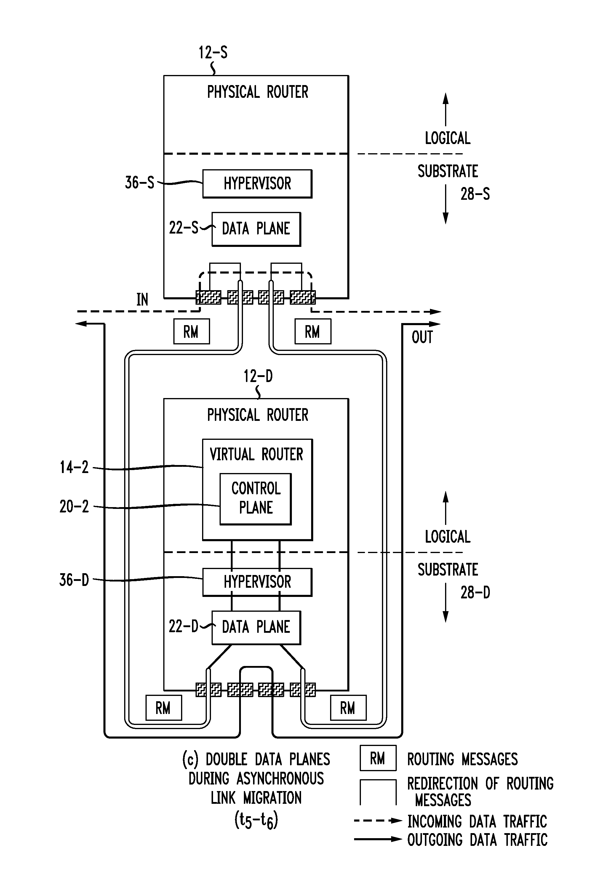
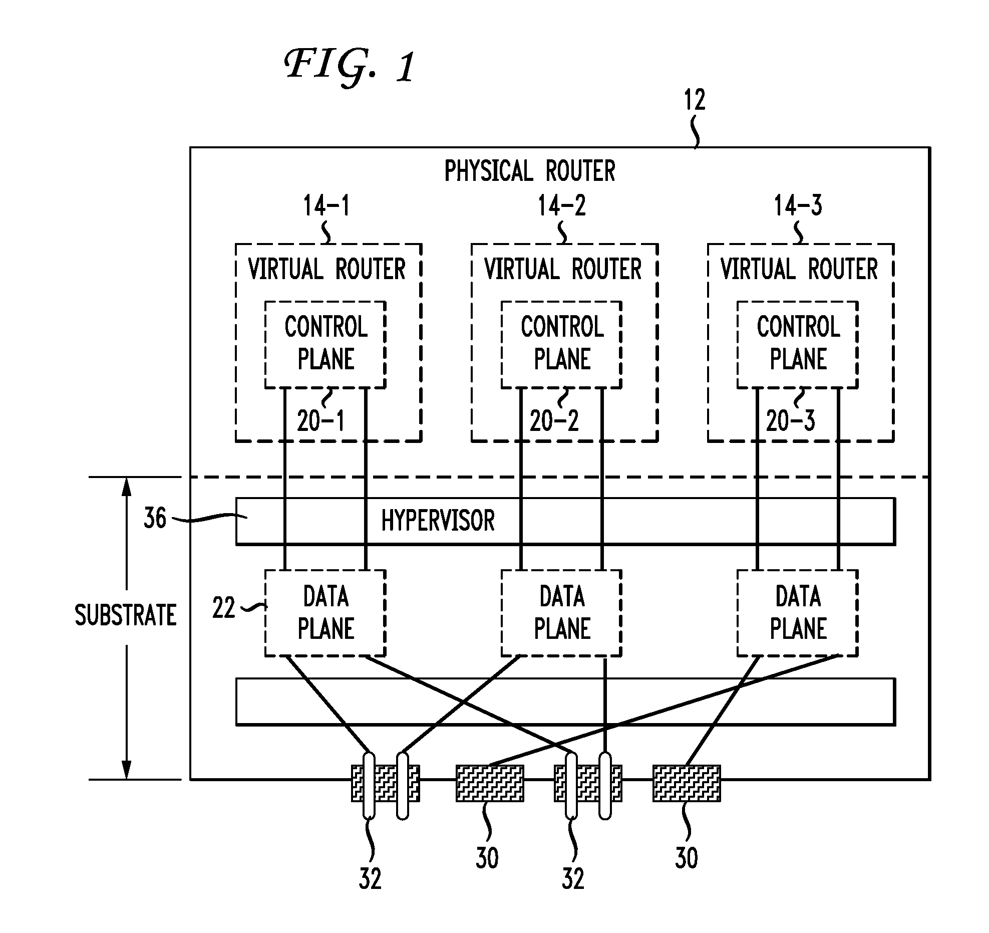
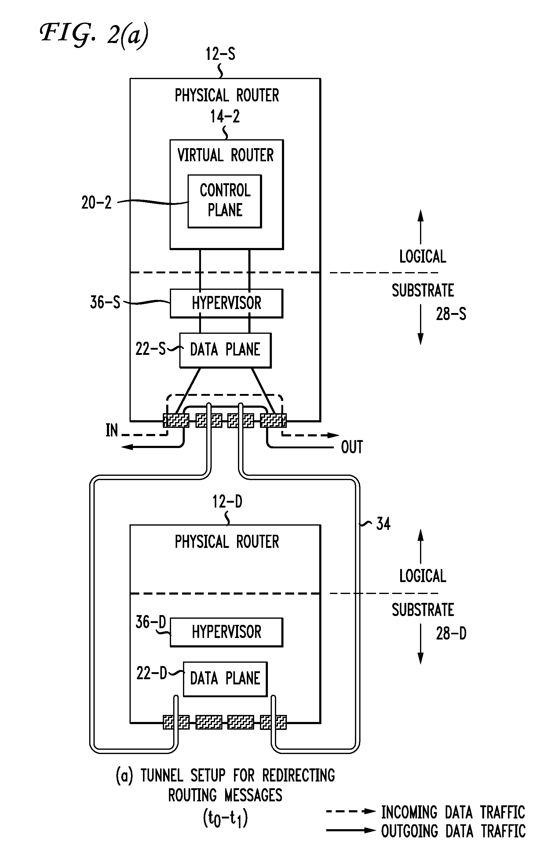
[0016]There are three basic building blocks to the live router migration strategy of the present invention: (1) router virtualization; (2) control and data plane separation; and (3) dynamic interface binding. Unlike regular servers, today's routers typically have physically separate “control” and “data” planes. In accordance with the present invention, this unique property is leveraged in the form of a “data-plane hypervisor” between the control and data planes which enables virtual routers to migrate across different data-plane platforms. In particular, three different techniques are used in accordance with the present invention to provide this implementation while minimizing control-plane downtime and eliminating data-plane disruption: (1) data-plane cloning, (2) remote control plane, and (3) double data planes.

[0017]FIG. 1 illustrates the architecture of an exemplary virtual router which can be used for live router migration in accordance with the present invention. As will be di...


PUM


Abstract

Live router migration is implemented by separating the logical features of a virtual router from its physical features. Tunnels are established between a source (physical) router and a destination (physical) router, allowing the control plane of the virtual router being migrated to send and receive messages from the destination router. The control plane information is then transferred to the destination router, which functions to clone the data plane at the destination router. Outgoing links from the destination router are then be established. The double appearance of the data plane at both the source and destination routers allows for the data plane information to be transferred asynchronously over to the destination router. Once all of the data plane information has been transferred, incoming data traffic links at the destination router can be established and the tunnels between the routers taken down.

Description

TECHNICAL FIELD[0001]The present invention relates to router migration during network management and, more particularly, to a network-management primitive which allows for (virtual) routers to freely move from one physical node to another without impacting data traffic.BACKGROUND OF THE INVENTION[0002]Network management is widely recognized as one of the most important challenges facing the Internet. Indeed, the cost of personnel and systems which manage a network typically exceeds the cost of the underlying nodes and links. Additionally, most network outages are caused by operator errors, rather than equipment failures. From routine tasks such as “planned maintenance” to the less-frequent deployment of new protocols, network operators struggle to provide seamless service in the face of changes to the underlying network. Handling change is difficult because each change to the physical infrastructure requires a corresponding modification to the logical configuration of the routers (e...

Claims


Application Information

Patent Timeline
IPC IPC(8): H04L12/26H04L12/28
CPCH04L45/586
Inventor MERWE, JACOBUS VAN DERWANG, YI
Owner AT&T INTPROP I L P
Learn More