Method for interference randomization of physical uplink control channel

a control channel and uplink technology, applied in the field of wireless communication, can solve the problems of damage to the orthogonality of the cazac sequence in frequency domain, interference of the control channel of the ues in the cell with each other, and poor orthogonality, so as to improve the receipt performance of pucch and simplify the implementation

Active Publication Date: 2011-02-10
ZTE CORP
View PDF10 Cites 35 Cited by
  • Summary
  • Abstract
  • Description
  • Claims
  • Application Information

AI Technical Summary

Benefits of technology

[0041]From the above description, it can be seen that for the three cases in the present invention, the methods of control channel remapping in the second timeslot used by the UE have the same basic principle and all apply the prime-modulo methods, so as to have the advantages of uniform form and simple implementation. With the methods of the present invention, it can guarantee that the interference among the UEs multiplexed in one resource block or in one hybrid resource block is equalized and randomized in the sustained period of the control channel, thus the interference of the PUCCH of each UE in the cell is randomized and the receipt performance of PUCCH is improved.

Problems solved by technology

From the above content, it can be seen that the control channel of each UE which sends uplink control signaling in the PUCCH of one resource block in the cell is code division multiplexed, and in the ideal channel, the control channel of each UE in the cell is ideally orthogonal, in the practical channel however, the orthogonality of the control channel of each UE is damaged due to the channel fading delay and the Doppler shift because of the moving of UE, therefore, the control channels of the UEs in the cell are interfered with each other.
For ACK / NACK channel, the damage of orthogonality comes from two sides, on one side, the orthogonality of the CAZAC sequence in frequency domain is damaged due to the channel time delay spread, moreover the orthogonality is related to the difference of the cyclic shift of the CAZAC sequence used, for instance, the orthogonality is relatively poor in the delay fading channel when the difference of the cyclic shift is relatively small, such as the adjacent cyclic shifts, while maintains well when the cyclic shifts have relatively large interval; on the other side, the orthogonal codes in time domain are damaged due to the Doppler shift and the damage degree is related to the moving speed of UE.
For CQI channel, the reason of the damage to the orthogonality is that the orthogonality of CAZAC sequence in frequency domain is damaged because of the time delay spread of the channel.
As mentioned above, since the hopping patterns of cyclic shifts of CAZAC sequence are cell-specific, that is, the hopping patterns of all UEs in the cell are the same, therefore, if two UEs use control channels which interfere with each other severely, the interference in the sustained period of control channel is relatively severe.

Method used


Image

  • Method for interference randomization of physical uplink control channel
  • Method for interference randomization of physical uplink control channel
  • Method for interference randomization of physical uplink control channel

Examples


first embodiment

[0082]In the first embodiment, as shown in FIG. 4, only the UEs sending ACK / NACK are multiplexed in one resource block, and the normal cyclic prefix is used in the PUCCH, the number of available OCs is 3, and in the same OC, the allowed cyclic shift interval ΔshiftPUCCH is 1, thus the number of UEs multiplexed to simultaneously send ACK / NACK in one resource block is N=c×NSCRB / ΔshiftPUCCH=3×12 / 1=36, UE selects the control channel CB1[i] in the first timeslot and thus CB2[g1(i, c, N)] in the second timeslot,

g(i,c,N)=g(i,3,36)=((i+1)×3)mod(36+1)−1;

[0083]For instance, UE1> uses the ACK / NACK control channel CB1[1] to send ACK / NACK information in the first timeslot, then:

g(1,3,36)=((1+1)*3)mod 37−1=5

[0084]Therefore, UE1> uses the ACK / NACK control channel CB2[5] to send ACK / NACK information in the second timeslot.

[0085]Also for instance, UE2> uses the ACK / NACK control channel CB1[2] to send ACK / NACK information in the first timeslot, then: g(2,3,36)=((2+1)*3)mod 37−1=8.

[0086]Therefore, UE2...

second embodiment

[0088]In the second embodiment, as shown in FIG. 5, only the UEs sending ACK / NACK are multiplexed in one resource block, and the normal cyclic prefix is used in the PUCCH, the number of available OCs is 3, and in the same OC, the allowed cyclic shift interval ΔshiftPUCCH is 2, thus the number of UEs multiplexed to simultaneously send ACK / NACK in one resource block is N=c×NSCRB / ΔshiftPUCCH=3×12 / 2=18, UE selects the control channel CB1[i] in the first timeslot and thus CB2[g1(i, c, N)] in the second timeslot,

g(i,c,N)=g(i,3,18)=((i+1)×3)mod(18+1)−1;

[0089]For instance, UE1> uses the ACK / NACK control channel CB2[5] to send ACK / NACK information in the second timeslot, and UE2> uses the ACK / NACK control channel CB2[8] to send ACK / NACK information in the second timeslot.

third embodiment

[0090]In the third embodiment, as shown in FIG. 6, only the UEs sending ACK / NACK are multiplexed in one resource block, and the normal cyclic prefix is used in the PUCCH, the number of available OCs c is 3, and in the same OC, the allowed cyclic shift interval is ΔshiftPUCCH=3, thus the number of UEs multiplexed to simultaneously send ACK / NACK in one resource block is N=c×NSCRB / ΔshiftPUCCH==3×12 / 3=12, UE selects the control channel CB1[i] in the first timeslot and thus CB2[g1(i, c, A)] in the second timeslot,

g(i,c,N)=g(i,3,12)=((i+1)×3)mod(12+1)−1;

[0091]For instance, UE1> uses the ACK / NACK control channel CB2[5] to send ACK / NACK information in the second timeslot, and UE2> uses the ACK / NACK control channel CB2[8] to send ACK / NACK information in the second timeslot.


PUM


Abstract

A method for interference randomization of physical uplink control channel (PUCCH), which is used in long term evolution (LTE) system, when multiple terminals multiplex PUCCH to transmit uplink control signallings, the difference of index of control channel resource used by any two terminals in the first timeslot of PUCCH is different from the difference of index of control channel resource used by the two terminals in the second timeslot of PUCCH. The invention can realize interference randomization between UEs that multiplex the same PUCCH.

Description

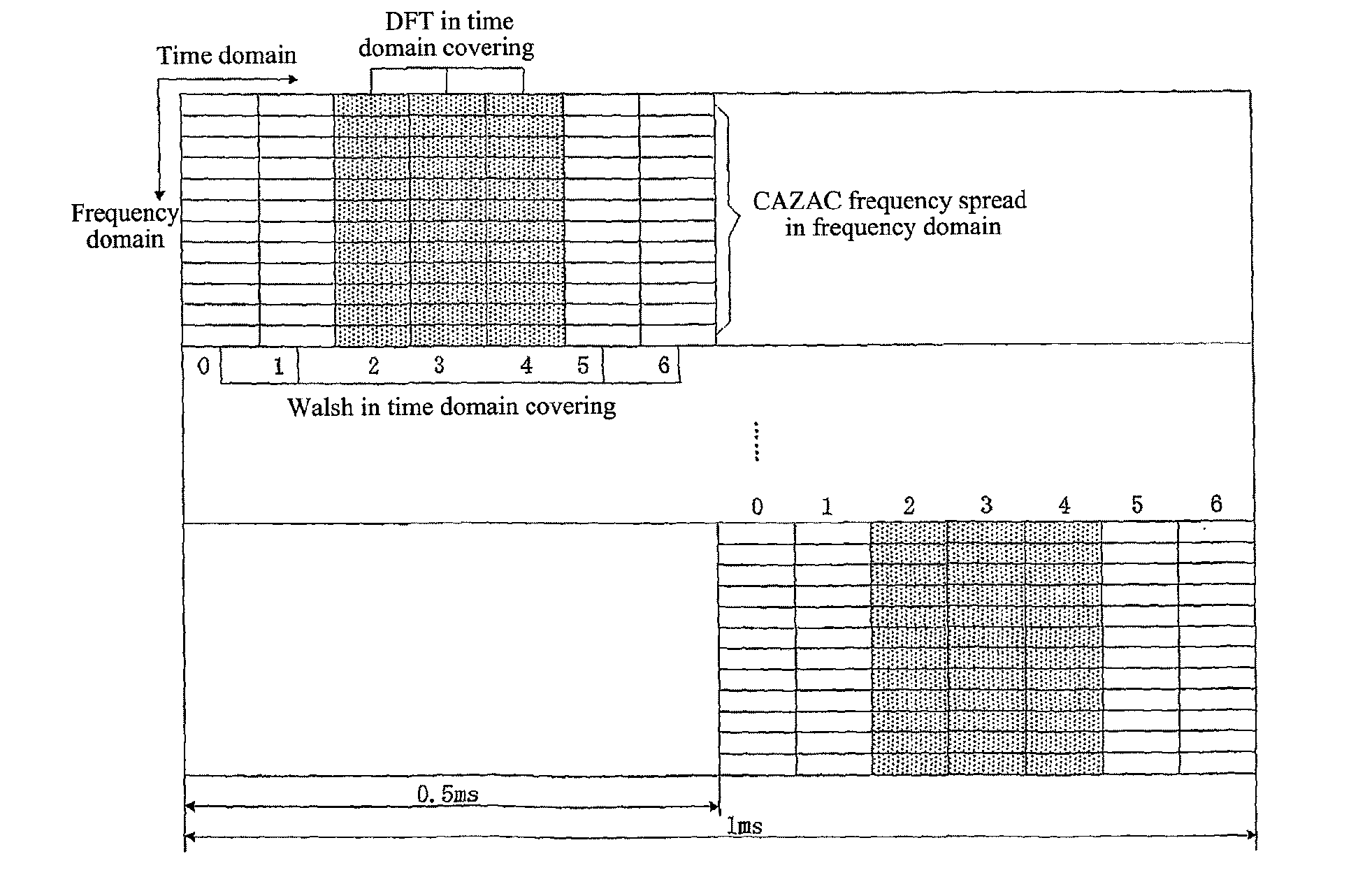
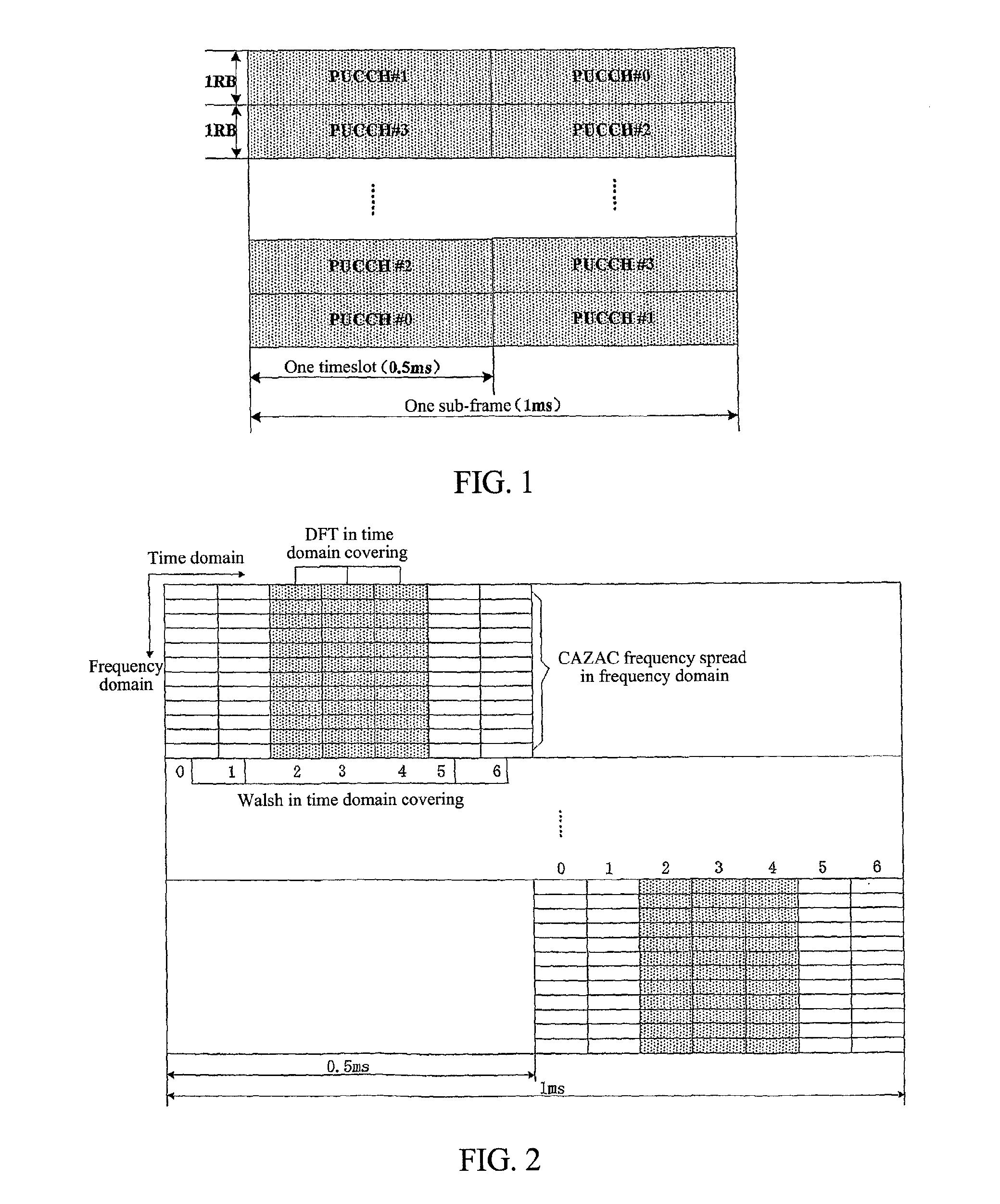
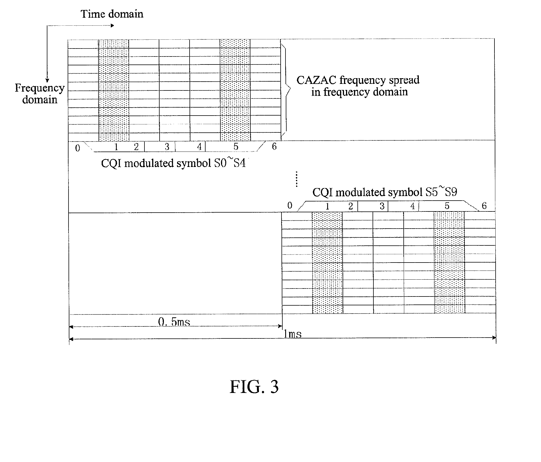
TECHNICAL FIELD [0001]The present invention relates to the field of wireless communication, and more especially, to method for interference randomization in a physical uplink control channel (PUCCH).BACKGROUND OF THE INVENTION[0002]To date, it is specified in Long Term Evolution (LTE) system that PUCCH is transmitted using the fixed time-frequency resource if User Equipment (UE) has no uplink data to send. Every UE that sends control signalings in the PUCCH of the same resource block in the cell uses one control channel through code division multiplexing. As shown in FIG. 1, one control channel for one UE occupies a bandwidth of one resource block (RB) (one resource block has 12 sub-carriers) in frequency domain, and two adjacent timeslots constitute one sub-frame, that is, 1 ms in time domain. According to different cyclic prefixes used by the current sub-frame, the number of symbols within the sub-frame is different. Moreover, the control channel frequency-hops in two timeslots to...

Claims


Application Information

Patent Timeline
Patent Type & Authority Applications(United States)
IPC IPC(8): H04J3/00
CPCH04J11/003H04J13/0059H04J13/0074H04J13/18H04L5/0055H04L1/0027H04L1/1854H04L5/0007H04L5/0053H04L1/0026H04L5/0073
Inventor XIA, SHUQIANGLIANG, CHUNLIDAI, BOHAO, PENG
Owner ZTE CORP
Why Eureka
Try Eureka