Crimped electric wire with terminal and method for producing the same

Inactive Publication Date: 2011-02-10
AUTONETWORKS TECH LTD +2
View PDF8 Cites 9 Cited by
  • Summary
  • Abstract
  • Description
  • Claims
  • Application Information

AI Technical Summary

Benefits of technology

[0026]In the portion (the upper portion of the barrel) constituting the upper face R of the barrel piece 42, since the upper face R is large, the barrel piece 42 is hard to be rounded. Hence, the thickness does not increase when a load is applied, whereby the rigidity is hard to be increased. However, since the tip end of the barrel piece 42 tends to be turned toward the bottom plate 41 due to the load applied to the upper portion of the barrel, the load applied to the upper face R of the barrel piece 42 easily concentrates on the bottom plate 41.
[0027]On the other hand, the barrel piece 42 shown in FIG. 8 does not rise in the same direction as the direction (vertical direction) in which the load is applied. In other words, the intermediate portion of the barrel shown in FIG. 7 falls down, thereby constituting part of the upper portion of the barrel. Hence, the intermediate portion of the barrel does not exist in FIG. 8. As a result, since the tip end of the barrel piece 42 is closer to the bottom plate 41, the load is easily applied from the tip end of the barrel piece 42 to the bottom plate 41. Hence, the bottom plate 41 is easy to be elongated.
[0028]In that respect, in the present invention, the terminal fitting 20 shown in FIG. 6 h

Problems solved by technology

Hence, when high compression crimping is performed, a problem is revealed in which the elongation of the electric wire crimping section is larger than that in the case of the copper electric wire.
Since high compression is required in the case of crimping the aluminum electric wire as described above, the elongation ratio of the terminal fitting inevitably becomes large.
On the other hand, if the compr

Method used


Image

  • Crimped electric wire with terminal and method for producing the same
  • Crimped electric wire with terminal and method for producing the same
  • Crimped electric wire with terminal and method for producing the same

Examples


Example

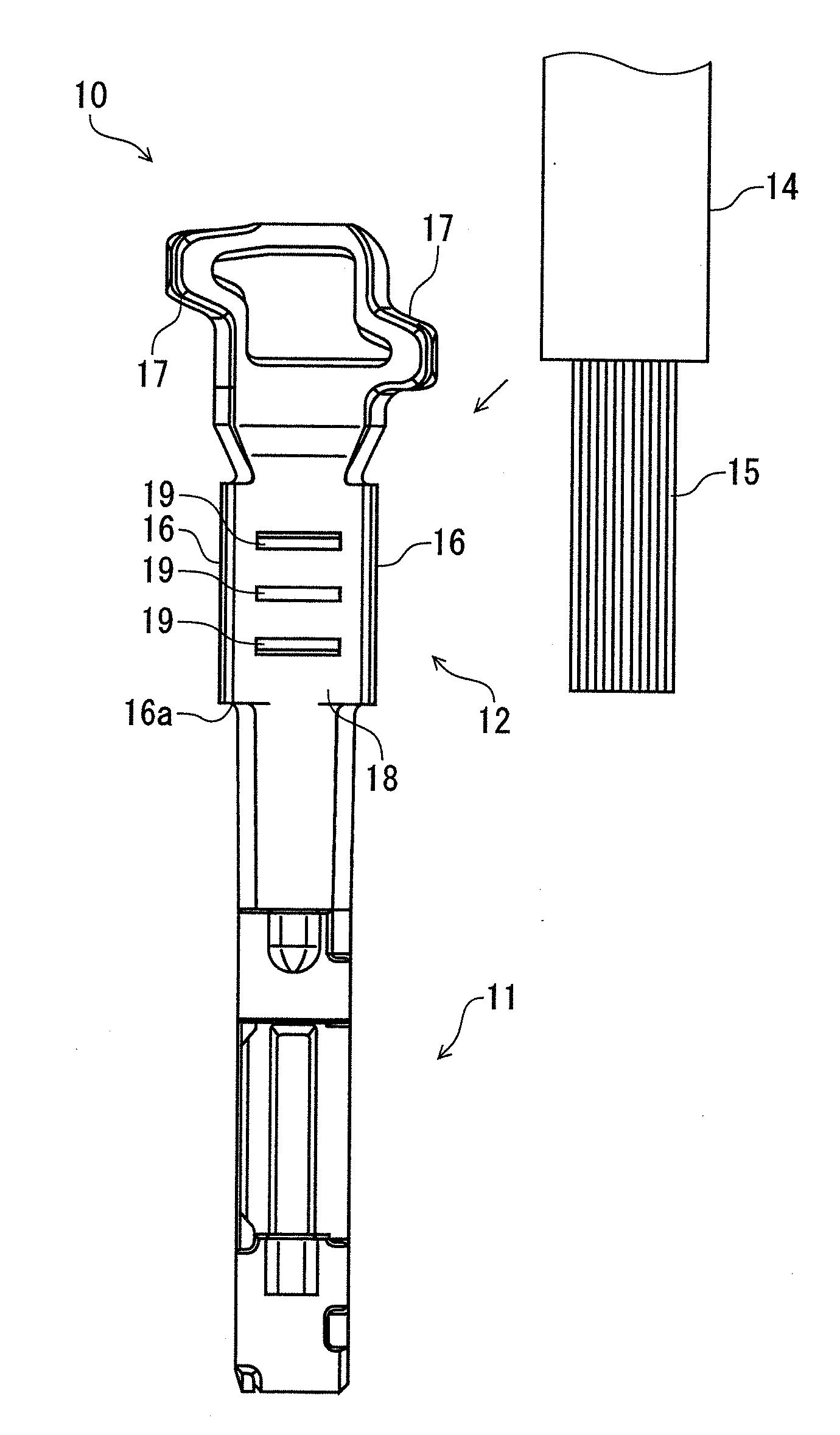
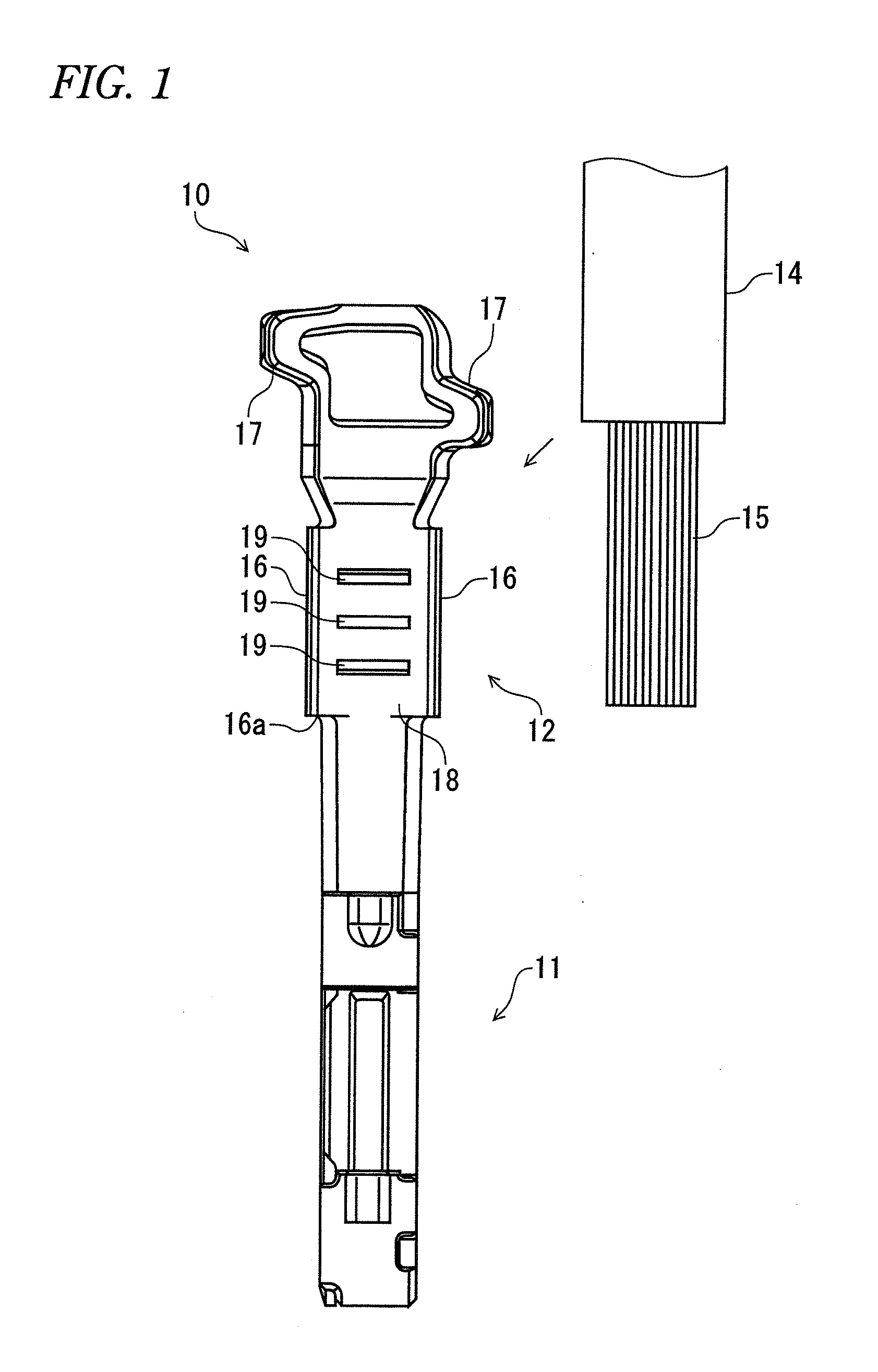
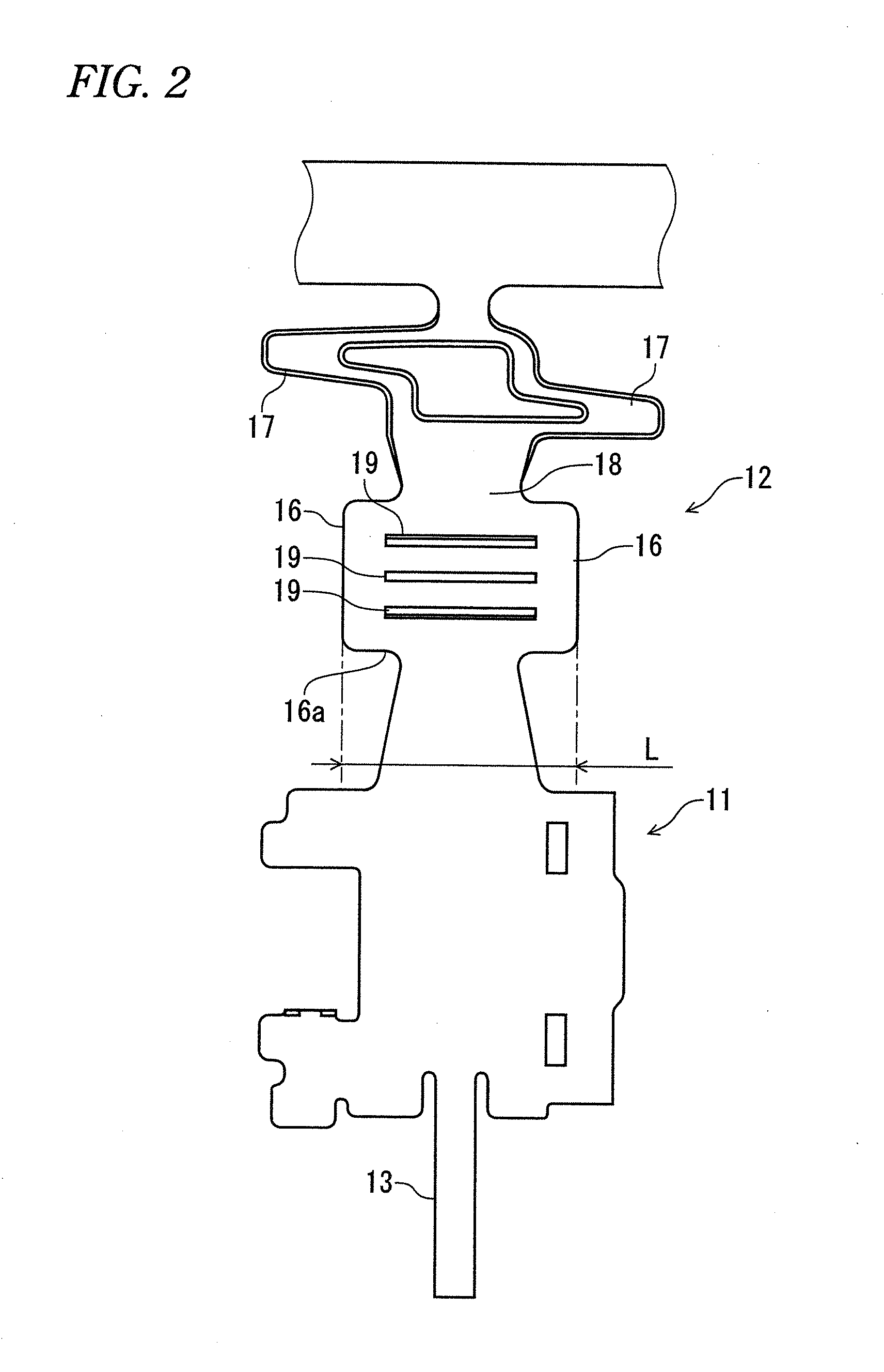
[0040]An embodiment according to the present invention will be described below referring to FIGS. 1 to 9. A crimped electric wire with a terminal according to the embodiment is configured so that a terminal fitting 10 is crimp-connected to the end of an electric wire 14. An example is described in which the terminal fitting 10 is used as a female terminal fitting. The overall structure of the terminal fitting 10 before crimping is shown in a plan view of FIG. 1. A hoop material made of a copper alloy sheet is stamped out using a press into a predetermined shape as shown in FIG. 2 and folded and bent so as to be formed into the state shown in FIG. 1, whereby the terminal fitting 10 is obtained.

[0041]As shown in FIG. 1, a terminal connection section 11 having a square cylindrical shape is formed on the tip end side (the lower side in the figure) of the terminal fitting 10, and an electric wire crimping section 12 is formed on the opposite side. An elastic contact piece 13 (see FIG. 2)...


PUM

PropertyMeasurementUnit
Fractionaaaaaaaaaa
Fractionaaaaaaaaaa
Compression ratioaaaaaaaaaa

Abstract

A crimped electric wire with a terminal, includes: an electric wire having a core wire made of aluminum or aluminum alloy; and a terminal fitting having an electric wire crimping section for crimping the core wire partly exposed from the electric wire, wherein: a value obtained by dividing the height of the electric wire crimping section by the width of the electric wire crimping section after the crimping of the electric wire crimping section is set to 0.5 or more and 0.6 or less; and the value obtained by dividing the gross cross-sectional area of the core wire after the crimping of the electric wire crimping section by the gross cross-sectional area of the core wire before the crimping of the electric wire crimping section is set to 55% or more and 65% or less.

Description

BACKGROUND OF THE INVENTION[0001]1. Field of the Invention[0002]The present invention relates to a crimped electric wire with a terminal and a method for producing the same.[0003]2. Description of the Related Art[0004]Generally, a terminal fitting equipped with an electric wire crimping section for crimping a core wire exposed at the end of an electric wire is known as a terminal fitting that is connected to the end of an electric wire. This electric wire crimping section has a pair of barrel pieces rising from both end fringes of the bottom plate of the terminal fitting. When the core wire is placed on the bottom plate and swaged using an anvil and a crimper in the vertical direction, the core wire is conductively connected to the electric wire crimping section.[0005]The issue of specifically determining what kind of shape is formed as the crimped shape of the core wire using the barrel pieces of the electric wire crimping section is generally controlled depending on the value of t...

Claims


Application Information

Patent Timeline
IPC IPC(8): H01R4/18H01R43/04
CPCH01R43/048H01R4/62Y10T29/49181H01R4/185H01R4/206H01R43/0488
Inventor KOBAYASHI, KAZUMASAOOTSUKA, TAKUJISHIMODA, HIROKI
Owner AUTONETWORKS TECH LTD
Why Eureka
Try Eureka