Water Management System

a water management system and water supply technology, applied in the direction of volume meters, instruments, electric devices, etc., can solve the problems of water unsafe to drink and people who have not paid their bills

Inactive Publication Date: 2011-02-10
PALAYUR SAJU ANTONY
View PDF47 Cites 63 Cited by
  • Summary
  • Abstract
  • Description
  • Claims
  • Application Information

AI Technical Summary

Benefits of technology

[0032]d) a second communication link to the Internet through which a user can monitor and control his water usage. The water usage can be converted to a dollar amount for the benefit of the user.
[0033]The water consumption monitoring and control system is also connected to pressure sensors. The received pressure information is compared to pre-entered criteria. An alarm is generated if the pressure information does not conform to the pre-entered criteria. For example, a low pressure may indicate breakage or leak in a water pipe. This alarm is used to generate a message over the Internet in the form of email, tweet or text. Text messaging could use, for example, the Short Message Service (SMS) protocol.
[0034]The water consumption monitoring and control system is also connected to water shut-off valves. The received pressure information is compared with pre-entered criteria. A shut-off signal is generated if the pressure information does not conform to the pre-entered criteria. This shut-off signal is sent to the shut-off valves.

Problems solved by technology

Possible reasons for shutting off the water supply is that the utility company may determine that the water is unsafe to drink or that customers have not paid their bills.

Method used


Image

  • Water Management System
  • Water Management System
  • Water Management System

Examples


Embodiment Construction

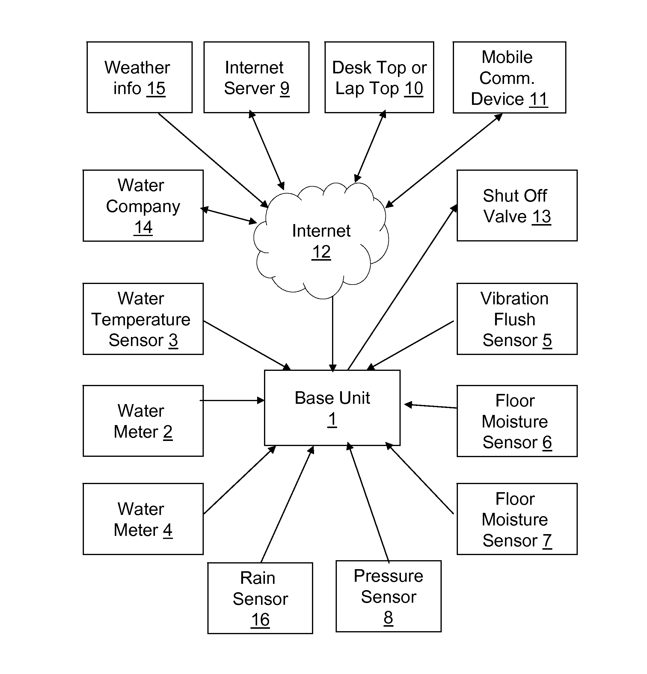
[0046]The system block diagram of the invention is shown in FIG. 1. It comprises the following components:[0047]a) A display / control panel called the base unit.1[0048]b) A series of sensors including water temperature sensors 3, water pressure sensors 8, floor moisture sensors 7, vibration flush sensors 5, water meters 2, 4, rain sensors / gauge 16.[0049]c) A series of actuators, such as shut off valves 13.[0050]d) Communication links to several entities located on the Web in particular a server 9, a utility company 14 (water company), a weather information service 15 and user mobile communication devices (e.g., cell phones)[0051]e) An internet server 9[0052]f) Desk top or lap top computers 10[0053]g) User mobile communication devices 11

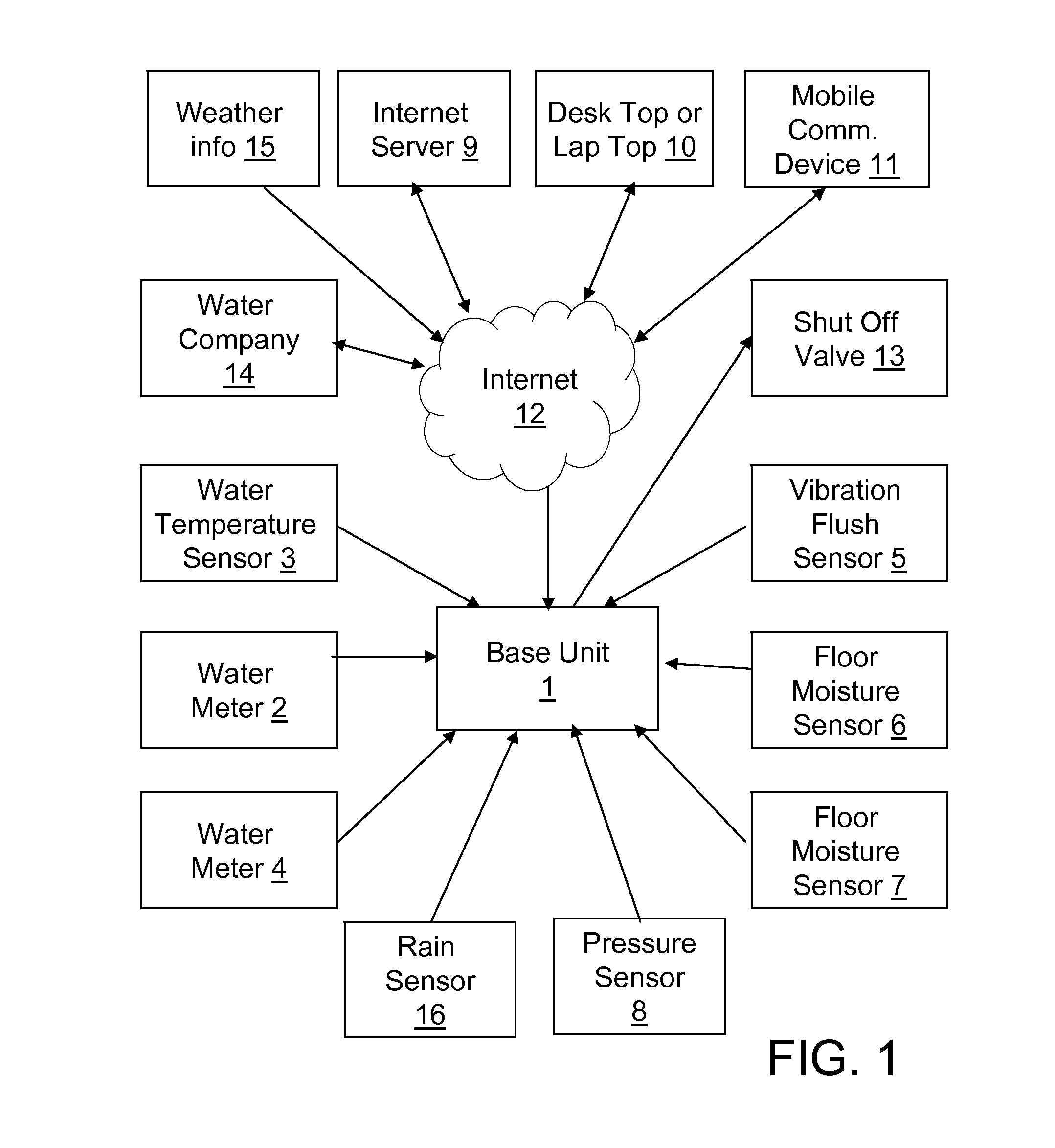
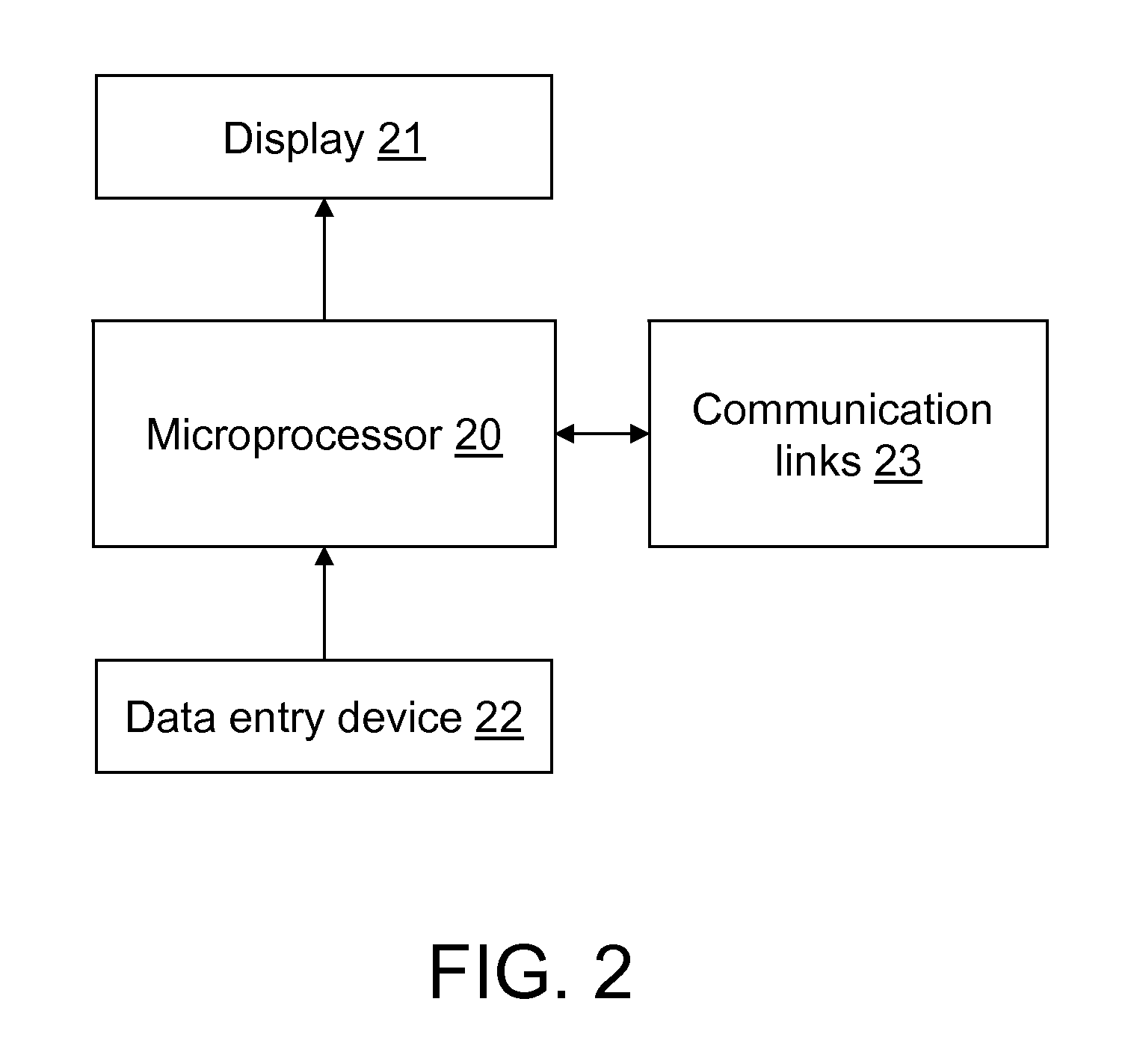
[0054]The base unit 1 is configured to monitor and control water consumption. The block diagram of the base unit is shown in FIG. 2. It comprises a microcontroller 21, a display 21, a data entry device 22 and at least one communication link 23.

[0055]Th...


PUM


Abstract

This invention is a water consumption monitoring and control system comprised of a base unit, itself comprising a display and a data entry device, a microprocessor, a communication link to water meters, pressure sensors, temperature sensors, flush toilet vibration sensors and shut-off valves. In addition the base unit has access to the Internet and can access a server which holds a database of water conservation information. This database includes watering advisories from the local government, and weather information from the weather office. The server runs an algorithm and generates control data which is sent to the base unit.

Description

FIELD OF THE INVENTION[0001]This invention claims the benefit of U.S. Provisional Applications No. 61 / 346,267, titled “Intelligent data logging, analysis system and / or subscription service for single and multi-site synchronous data, not limited to wind, solar analysis and water conservation applications” filed on May 19, 2010, and U.S. Provisional Applications No. 61 / 253,199 titled “Intelligent data logging and analysis system for single and multi-site synchronous data, not limited to wind and solar analysis applications and subscription service” filed on Oct. 20, 2009. Both of these applications are hereby incorporated by reference. Applicant claims priority pursuant to 35 U.S.C. Par 119(e)(i). The present invention relates to the monitoring and control of water consumption.BACKGROUND[0002]Freshwater is vital to health and to the economy, and reliable access to it is becoming increasingly important as the human population on Earth increases. Yet its availability is limited. Conserv...

Claims


Application Information

Patent Timeline
Patent Type & Authority Applications(United States)
IPC IPC(8): G05D7/06G06F17/00G01F1/00G01R21/00G06F19/00G08B21/00
CPCG06Q50/06G01F15/063Y02A20/00
Inventor PALAYUR, SAJU ANTHONY
Owner PALAYUR SAJU ANTONY
Why Eureka
Try Eureka