Identification system and method using highly collimated source of electromagnetic radiation

a technology of electromagnetic radiation and identification system, which is applied in the direction of optical radiation measurement, instruments, and using reradiation, can solve the problems of not being able to identify and detect the bulk of the distinguishable characteristics of the scene, and becoming increasingly difficult, so as to achieve sufficient strength, sufficient strength, and sufficient strength

Active Publication Date: 2011-02-17
9609385 CANADA INC
View PDF20 Cites 11 Cited by
  • Summary
  • Abstract
  • Description
  • Claims
  • Application Information

AI Technical Summary

Benefits of technology

[0007]The present invention addresses the above and other drawbacks by providing an identification system for identifying an asset. The system comprises an imaging device comprising an array of detectors sensitive to wavelengths within a predetermined band and a display, and a beacon positioned in proximity to the asset and at a distance from the imaging device. The beacon emits a beam of radiation comprised of wavelengths within the predetermined band and having a predetermined width at the distance. The beam is of sufficient strength such that when the beam is incident on the array, an image of the beam projected on the display has a relative width which is greater than the predetermined width.
[0008]In accordance with the present invention, there is also provided a method for identifying an asset in a system comprising an imaging device comprising an array of detectors sensitive to wavelengths within a predetermined band and a display, the asset positioned at a distance to the imaging device. The method comprises positioning a beacon in proximity to the asset, emitting using the beacon a beam of radiation comprised of wavelengths within the predetermined band and having a predetermined width at the distance, and directing the beam towards the imaging device. The beam is of sufficient strength such that when the beam is incident on the array, an image of the beam projected on the display has a relative width which is greater than the predetermined width.
[0009]Still in accordance with the present invention, there is also provided a beacon for use in an identification system for identifying an asset, the system comprising an imaging device comprising an array of detectors sensitive to wavelengths within a predetermined band and a display. The beacon comprises a source of radiation positioned in proximity to the asset and at a distance from the imaging device and a power supply for operating the source of radiation. The source of radiation emits a beam of radiation comprised of wavelengths within the predetermined band and having a predetermined width at the distance. The beam is of sufficient strength such that when the beam is incident on the array, an image of the beam projected on the display has a relative width which is greater than the predetermined width.

Problems solved by technology

This becomes increasingly difficult when forces move covertly through unknown combat zones with limited visibility.
Although the radiation they emit is invisible to the human eye, a major disadvantage of these emitters is that they are highly visible via night vision systems (NVS), which are commonplace in military applications.
However, one drawback of thermal imaging systems is that they typically do not allow to identify and detect the bulk of a scene's distinguishable characteristics (i.e. people, places, or objects).
In particular, in military applications, an observer cannot determine whether the displayed thermal image represents a “friendly” soldier (i.e. on their team) or an enemy as only the heat generated by the soldier is imaged on the thermal imaging device.
One drawback of such prior art thermal beacons, however, is that they typically rely on heating a blackbody (such as conductive plate or the like) to generate emissions in the infrared range.
As a result, a significant delay is typically experienced between successive beacon flashes as the beacon is heated and subsequently cooled and as a result is typically unsatisfactory for signalling applications without the use of a complex shuttering system.
Another drawback of such prior art devices is that blackbody radiation is inherently omnidirectional in nature and as a result the distance over which the beacon can be detected by the IR imaging equipment is limited.
Still another disadvantage is that even if the beacon is proximate enough that it can be detected using the IR imaging equipment, the image presented to the operator on the display of the equipment as a result of the radiation emitted by the beacon is small relative to the entire field of view (in many cases just a single pixel) and therefore may go undetected by all but the most vigilant of operators.

Method used


Image

  • Identification system and method using highly collimated source of electromagnetic radiation
  • Identification system and method using highly collimated source of electromagnetic radiation
  • Identification system and method using highly collimated source of electromagnetic radiation

Examples


Embodiment Construction

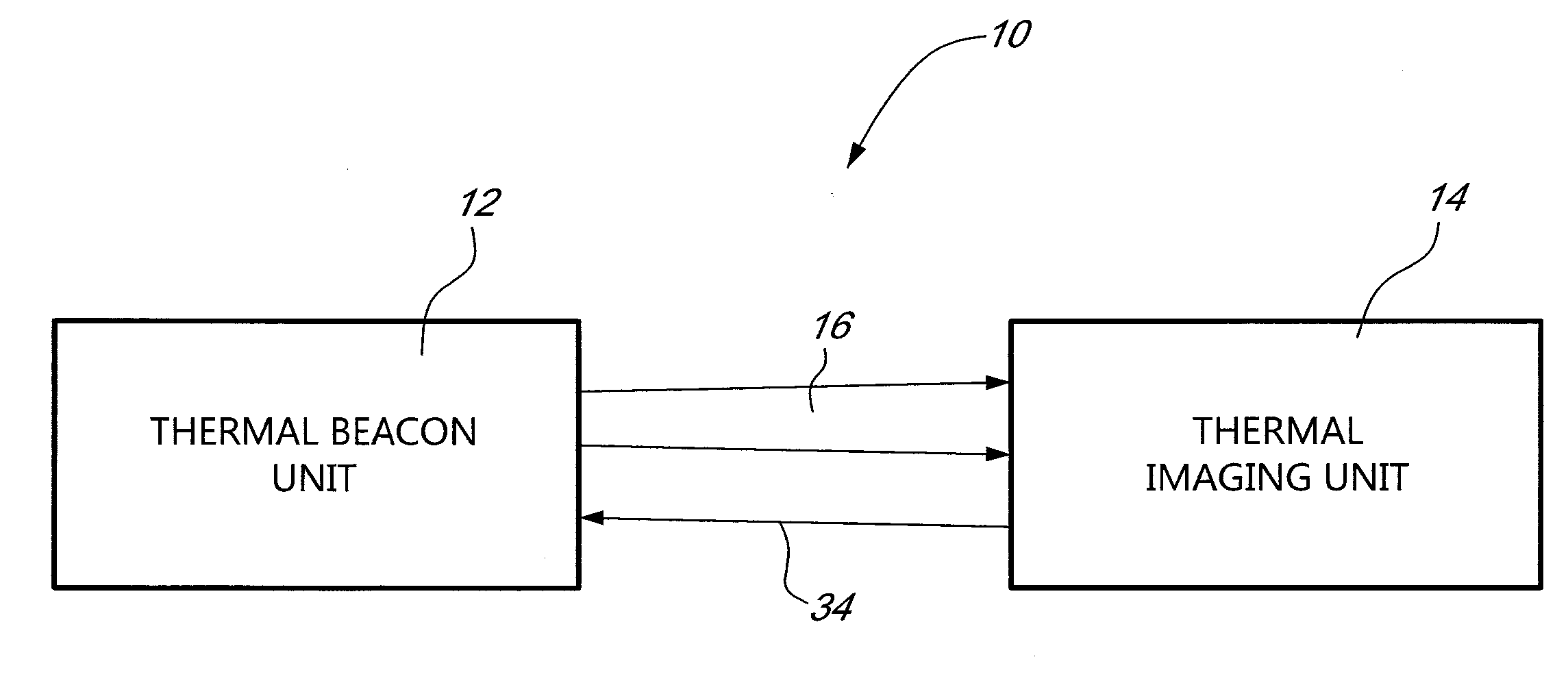
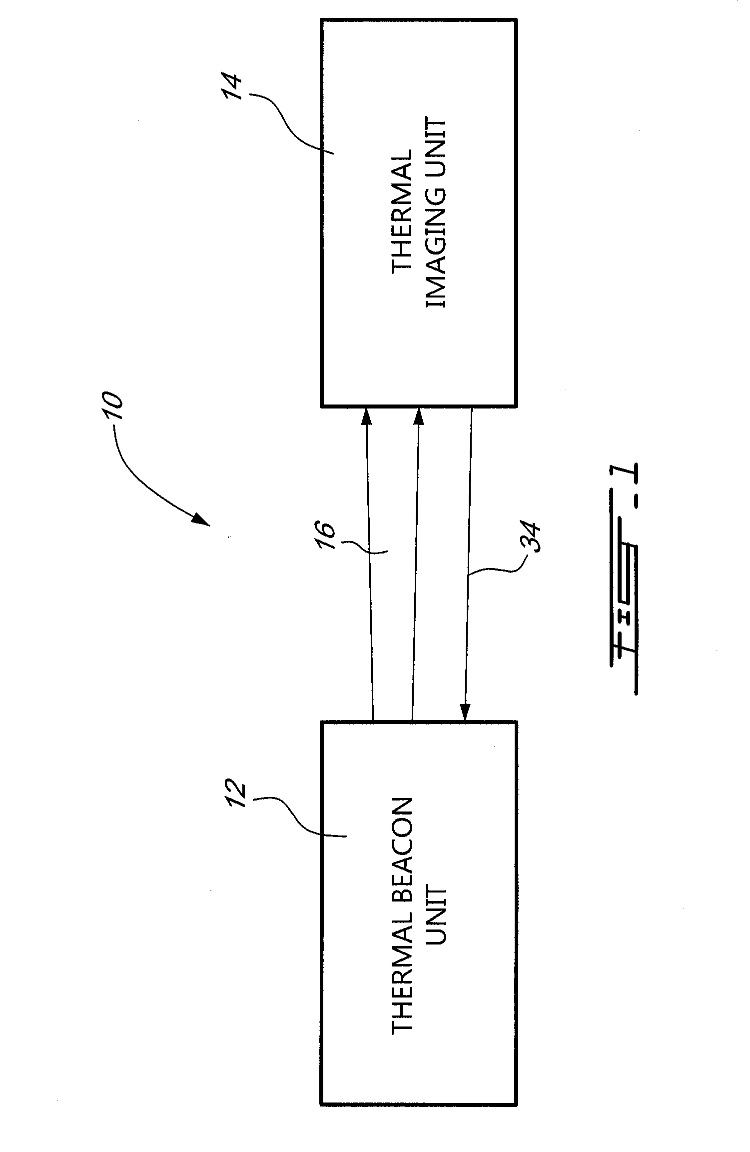
[0015]Referring now to FIG. 1, a thermal beacon identification system, generally referred to using the reference numeral 10, will now be described. The system 10 comprises a thermal beacon unit 12 and a thermal imaging unit 14 positioned at a distance thereto. In operation, the thermal beacon unit 12 emits radiation 16 projected in the direction of the thermal imaging unit 14 for identification of the thermal beacon unit 12 and associated carrier (soldier, vehicle, or the like). When detected by the thermal imaging unit 14, an image of the radiation 16 is displayed as a spot on the thermal imaging unit 14, thus eliciting the attention of a viewer observing a scene through it. The system 10 therefore allows for easy visual identification of specific locations, people, items, targets, and the like through the thermal imaging unit 14.

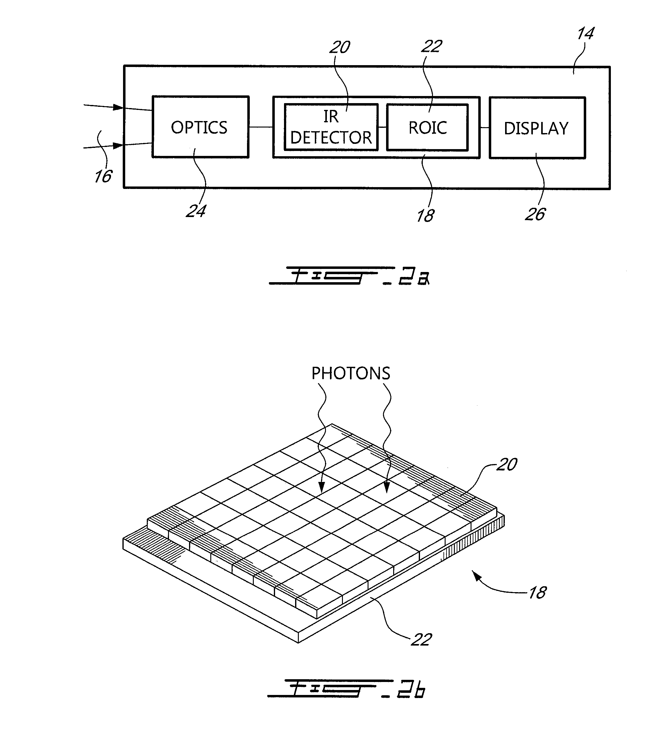
[0016]Referring now to FIGS. 2a and 2b in addition to FIG. 1, the thermal imaging unit 14 illustratively comprises an array of sensing elements 18, also r...


PUM


Abstract

An identification system and method comprising a beacon unit using a highly collimated source of electromagnetic radiation, which emits towards a thermal imaging unit highly directional radiation. In this manner, improved visual identification of the beacon unit and the carrier associated therewith through the imaging unit can be achieved over both short and long distances. In particular, detection of the beacon unit is aided by emitting highly collimated radiation with high power density at great distances. When detected by the sensor array, an image of the emitted radiation is indeed displayed as a bright spot of light on the display, thus eliciting the attention of a viewer observing a scene through the imaging unit. Blooming of an array of sensing elements provided in the imaging unit may further be fostered by delivering a great amount of power to the imaging unit, thus improving detection of the beacon unit.

Description

CROSS REFERENCE TO RELATED APPLICATIONS[0001]This application claims priority on U.S. Provisional Application No. 60 / 990,410, filed on Nov. 27, 2007 and which is herein incorporated by reference in its entirety.FIELD OF THE INVENTION[0002]The present invention relates to an identification system and method using a highly collimated source of electromagnetic radiation. In particular, the present invention relates to a beacon unit, which emits highly directional radiation towards a thermal imaging unit for secure and / or identification as friend or foe. The beacon unit may also be used to shield activities, equipment, etc., in the vicinity of the beacon unit from the operator of a thermal imaging unit.BACKGROUND OF THE INVENTION[0003]In military applications, secure and covert identification of an asset as friend or foe, also referred to as Identification Friend or Foe (IFF) is of the utmost importance. Indeed, it is primordial for military platform commanders to be able to accurately ...

Claims


Application Information

Patent Timeline
Patent Type & Authority Applications(United States)
IPC IPC(8): G01J5/20H01J40/14
CPCG01J1/04G01J1/0411G01V9/005G01J2005/0077G01S17/74G01J1/4228
Inventor FORD, TIMOTHY D.F.STACK, CASEY
Owner 9609385 CANADA INC
Why Eureka
Try Eureka