Information processing apparatus, and signal transmission method

a technology which is applied in the field of information processing apparatus and signal transmission method, can solve the problems of additional cost relating to cables and connectors, electromagnetic interference (emi) to the radio wave of a mobile phone, and the desire for simple movement of the hinge portion, etc., and achieve the effect of efficient data transmission

Inactive Publication Date: 2011-02-17
SONY CORP
View PDF6 Cites 31 Cited by
  • Summary
  • Abstract
  • Description
  • Claims
  • Application Information

AI Technical Summary

Benefits of technology

[0023]According to the embodiments of the present invention described abo...

Problems solved by technology

A very complicated movement is desired of the hinge portion to achieve such shape.
As a result, electromagnetic interference (EMI) to the radio wave of a mobile phone or the like is caused by the signal that is serially transmitted.
Furthermore, if the number of signal lines increase, it will result in additional cost relatin...

Method used


Image

  • Information processing apparatus, and signal transmission method
  • Information processing apparatus, and signal transmission method
  • Information processing apparatus, and signal transmission method

Examples


first embodiment

1: First Embodiment

[0051]The first embodiment of the present invention will be described. The present embodiment proposes a method of efficiently transmitting data by using two coaxial cables. Additionally, one 2-core coaxial cable or a shielded 2-core flexible cable may be used instead of two coaxial cables. However, in the following description, a case where two coaxial cables are used will be described as an example for the sake of explanation.

[0052]100>

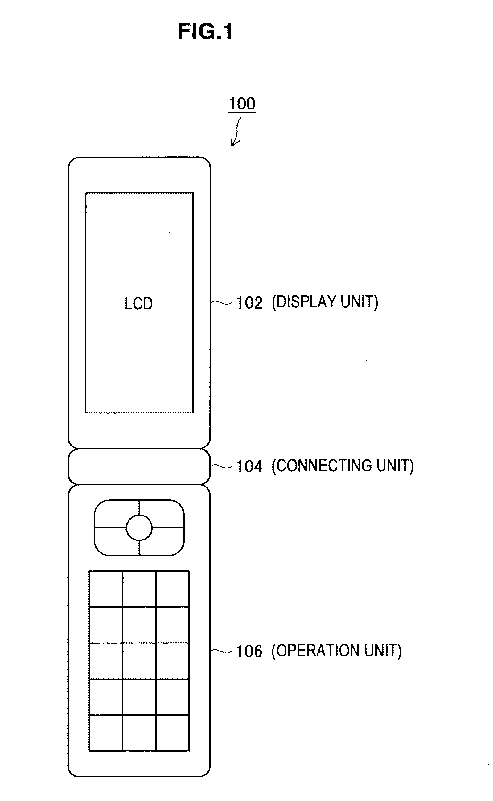
[0053]First, the structure of a mobile terminal 100 assumed in the present embodiment will be briefly described with reference to FIG. 1. FIG. 1 is an explanatory diagram showing the structure of the mobile terminal 100 assumed in the present embodiment. In this specification, a folding mobile phone is assumed for the sake of explanation, but the application range of the technology according to the present embodiment is not limited to such. For example, the technology according to the present embodiment can be applied to a noteboo...

second embodiment

2: Second Embodiment

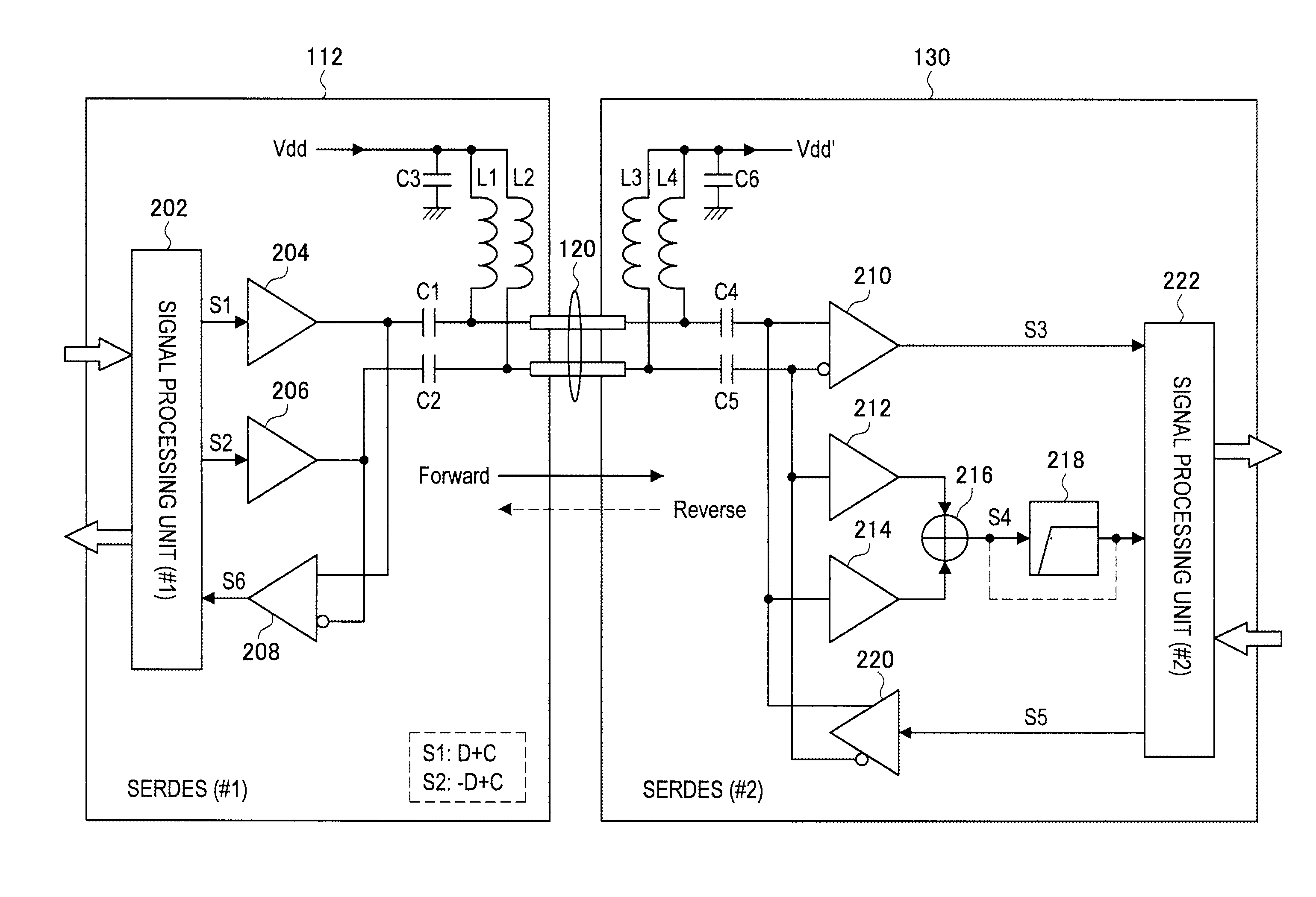
[0164]Next, the second embodiment of the present invention will be described. This embodiment relates to a technology for realizing bidirectional full-duplex transmission by using two coaxial cables. Additionally, one 2-core coaxial cable or one shielded 2-core flexible cable can also be used instead of two coaxial cables. However, in the following description, a case where two coaxial cables are used will be described as an example for the sake of explanation.

[0165]300>

[0166]The functional configuration of a mobile terminal 300 according to the present embodiment will be described with reference to FIG. 11. FIG. 11 is an explanatory diagram showing an example of the functional configuration of a mobile terminal 300 according to the present embodiment. Note that only the functional configurations of serializers / deserializers (SERDES (#1), SERDES (#2)) provided in the mobile terminal 300 are shown in FIG. 11, and the description of other structural elements is o...


PUM


Abstract

Provided is an information processing apparatus which includes a first module including a signal addition unit that generates an addition signal by adding a data signal to a clock, a signal subtraction unit that generates a subtraction signal by subtracting the data signal from the clock, a first signal transmission unit that transmits the addition signal through a first transmission line, and a second signal transmission unit that transmits the subtraction signal through a second transmission line, and a second module including a data component extraction unit that extracts a component of the data signal by subtracting the subtraction signal received through the second transmission line from the addition signal received through the first transmission line, and a clock component extraction unit that extracts a component of the clock by adding the subtraction signal received through the second transmission line to the addition signal received through the first transmission line.

Description

BACKGROUND OF THE INVENTION[0001]1. Field of the Invention[0002]The present invention relates to an information processing apparatus, and a signal transmission method.[0003]2. Description of the Related Art[0004]Most information processing apparatuses such as mobile phone and notebook personal computer (hereinafter, a notebook PC) use a movable member for a hinge portion connecting a main body to be operated by a user and a display portion on which information is displayed. However, a large number of signal lines and a power line pass through the hinge portion. Accordingly, from a standpoint of maintaining reliability of the wiring, a method of reducing the number of signal lines passing through the hinge portion as much as possible is desired. For this reason, it is deemed preferable nowadays to use a serial transmission scheme that is capable of reducing the number of signal lines, instead of a parallel transmission scheme, for data transmission performed between the main body and...

Claims


Application Information

Patent Timeline
IPC IPC(8): G09G5/00G06G7/14
CPCG09G5/006G09G2330/06G09G2330/021H04L25/0266H04L25/0276
Inventor FUKUDA, KUNIO
Owner SONY CORP
Why Eureka
Try Eureka