Light condensing film, backlight module and liquid crystal display
a liquid crystal display and light condensing film technology, applied in the field of liquid crystal display, can solve the problems of image washout caused by intense external light, difficult to distinguish displayed images, and strong outdoor light that may wash out the display image, and achieve good light condensing characteristics
- Summary
- Abstract
- Description
- Claims
- Application Information
AI Technical Summary
Benefits of technology
Problems solved by technology
Method used
Image
Examples
first embodiment
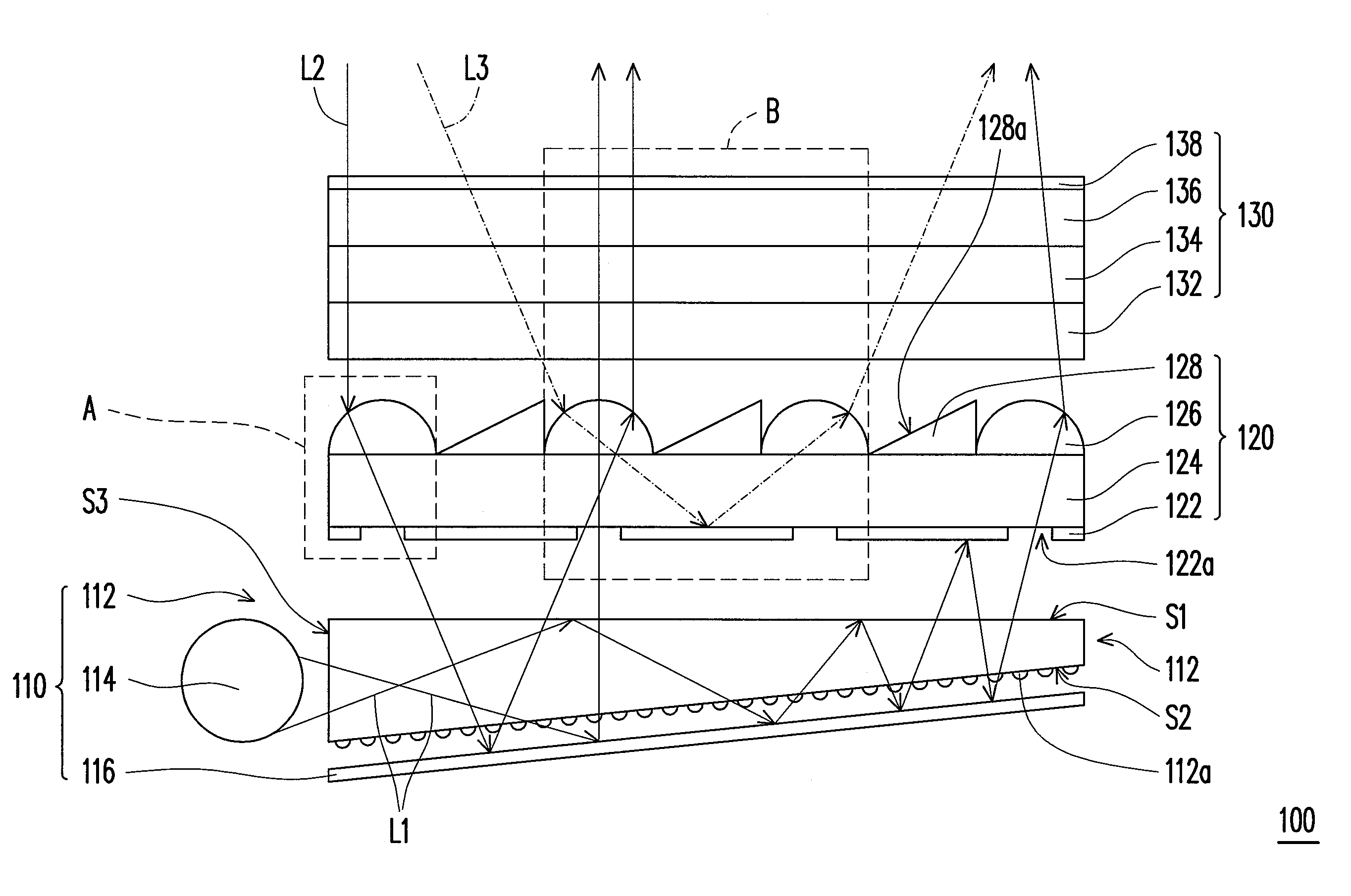
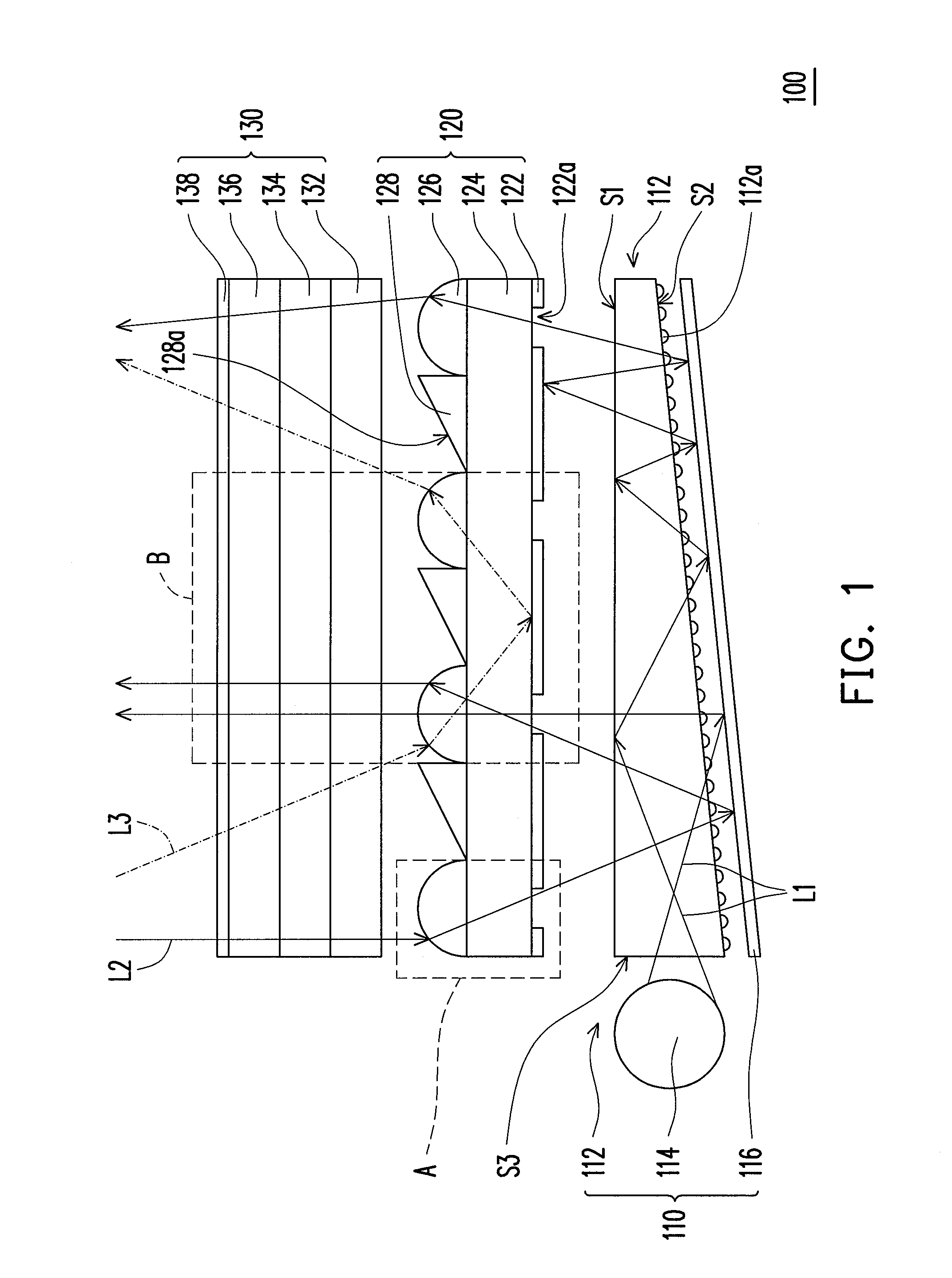
[0027]Referring to FIG. 1, the LCD 100 according to the embodiment of the invention includes a backlight unit 110, a light condensing film 120, and a liquid crystal panel 130. The backlight unit 110 is capable of providing an illumination beam L1. The light condensing film 120 is disposed on the backlight unit 110 and located in a transmission path of the illumination beam L1. In addition, the liquid crystal panel 130 is disposed on the light condensing film 120.
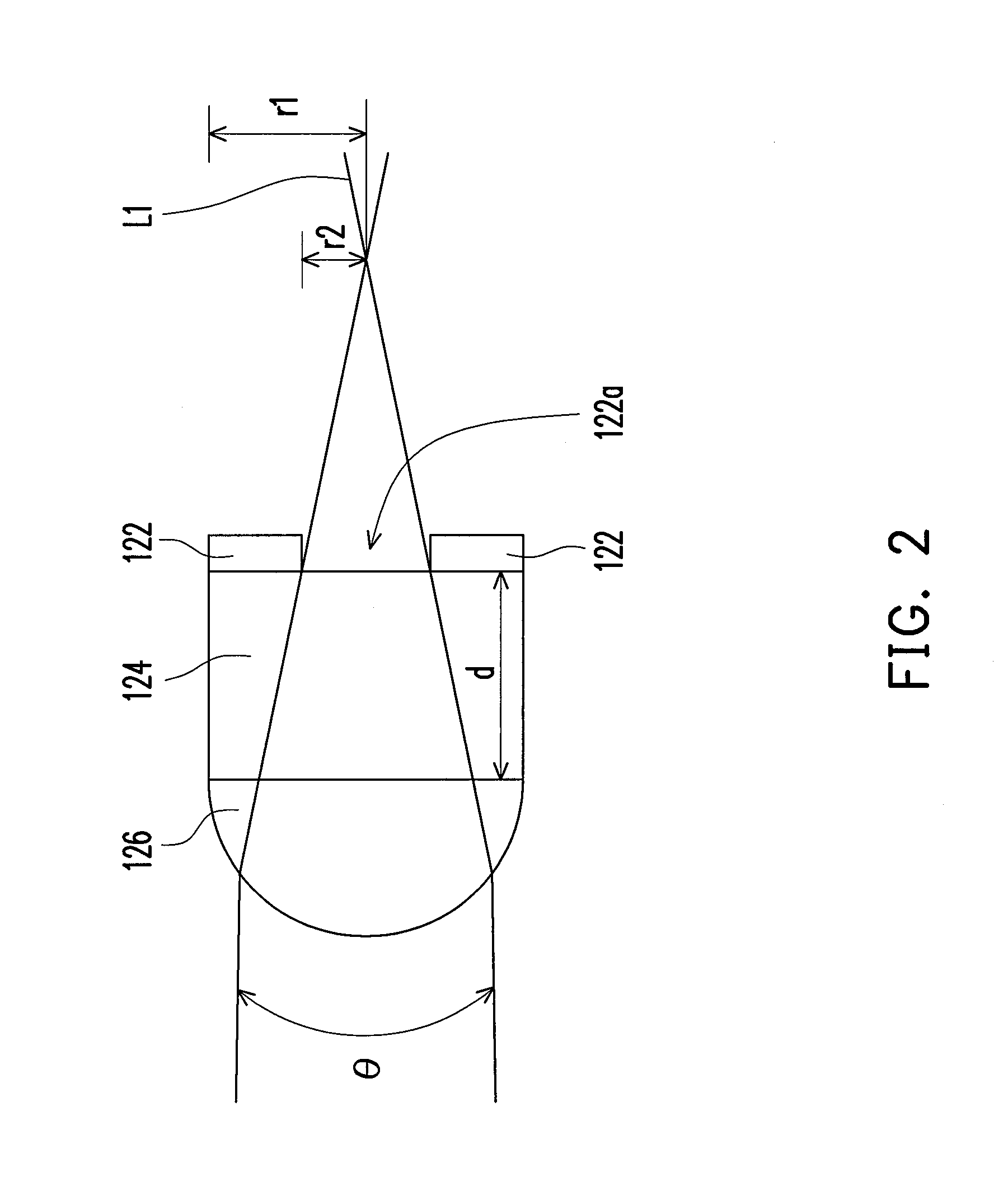
[0028]As shown in FIG. 1, the light condensing film 120 according to the embodiment includes a reflective unit 122, a light-transmissive substrate 124, a plurality of lenses 126, and a plurality of refractive units 128. The reflective unit 122 has a plurality of holes 122a passing through the reflective unit 122, and the holes 122a are distributed at the reflective unit 122. Each of the holes 122a is disposed around a focus of a corresponding one of the lenses 126, and the optical axis of the lenses 126 passes through the co...
second embodiment
[0042]The LCD 200 is similar to the LCD 100, and a difference between the LCD 100 and the LCD 200 lies in that the LCD 200 is a direct-type LCD.
[0043]Referring to FIG. 4, the LCD 200 according to the embodiment of the invention includes a backlight unit 210, a light condensing film 120, and a liquid crystal panel 130. The backlight unit 210 includes a light box 212, a plurality of light emitting devices 114, and a diffusion plate 214. As shown in FIG. 4, the light emitting devices 114 are disposed in the light container 212 and located between the diffusion plate 214 and an internal reflective surface 212a. Moreover, the diffusion plate 214 is disposed between each of the light emitting devices 114 and the light condensing film 120. The internal reflective surface 212a of the light box 212 may reflect the light emitted by the light emitting devices 114 towards the diffusion plate 214. In addition, the diffusion plate 214 is disposed on the light box 212 and located above the light e...
PUM
| Property | Measurement | Unit |
|---|---|---|
| reflectivity | aaaaa | aaaaa |
| viewing angle | aaaaa | aaaaa |
| viewing angle | aaaaa | aaaaa |
Abstract
Description
Claims
Application Information
 - R&D
- Intellectual Property
- Life Sciences
- Materials
- Tech Scout
- Unparalleled Data Quality
- Higher Quality Content
- 60% Fewer Hallucinations
Browse by: Latest US Patents, China's latest patents, Technical Efficacy Thesaurus, Application Domain, Technology Topic, Popular Technical Reports.
© 2025 PatSnap. All rights reserved.Legal|Privacy policy|Modern Slavery Act Transparency Statement|Sitemap|About US| Contact US: help@patsnap.com


