Universal contact lens posterior surface construction

a contact lens and posterior surface technology, applied in the field of contact lens posterior surface construction, can solve problems such as human vision deficiency, and achieve the effect of reducing optical distortion

Inactive Publication Date: 2011-02-17
SCI OPTICS INC
View PDF5 Cites 26 Cited by
  • Summary
  • Abstract
  • Description
  • Claims
  • Application Information

AI Technical Summary

Benefits of technology

[0008]Similarly, the applicants have found that the posterior surface of the optical zone of a lens can be modeled as an M-wave shape which is the same f...

Problems solved by technology

Most common defects in human vision are caused by the inability o...

Method used


Image

  • Universal contact lens posterior surface construction
  • Universal contact lens posterior surface construction
  • Universal contact lens posterior surface construction

Examples


Embodiment Construction

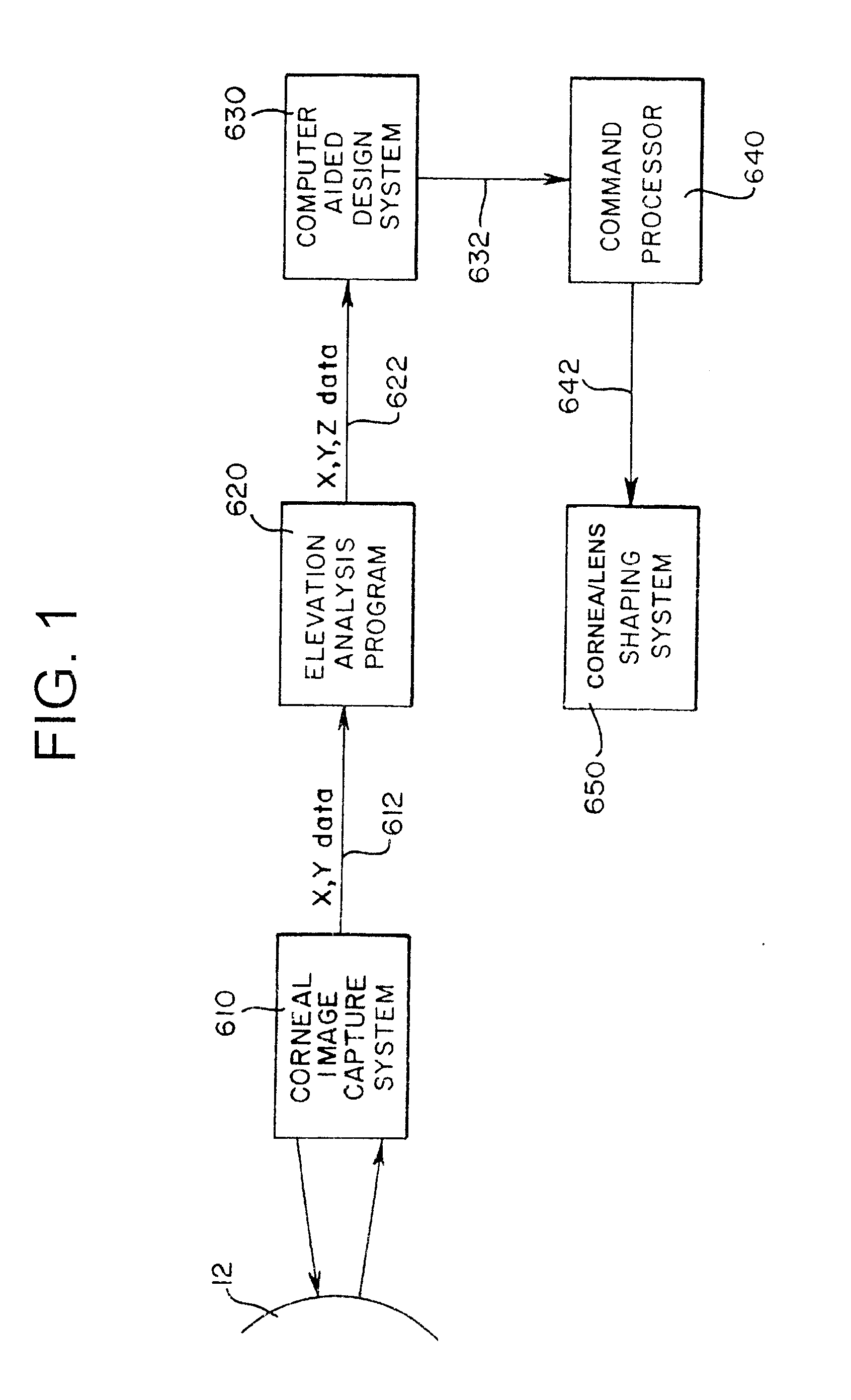
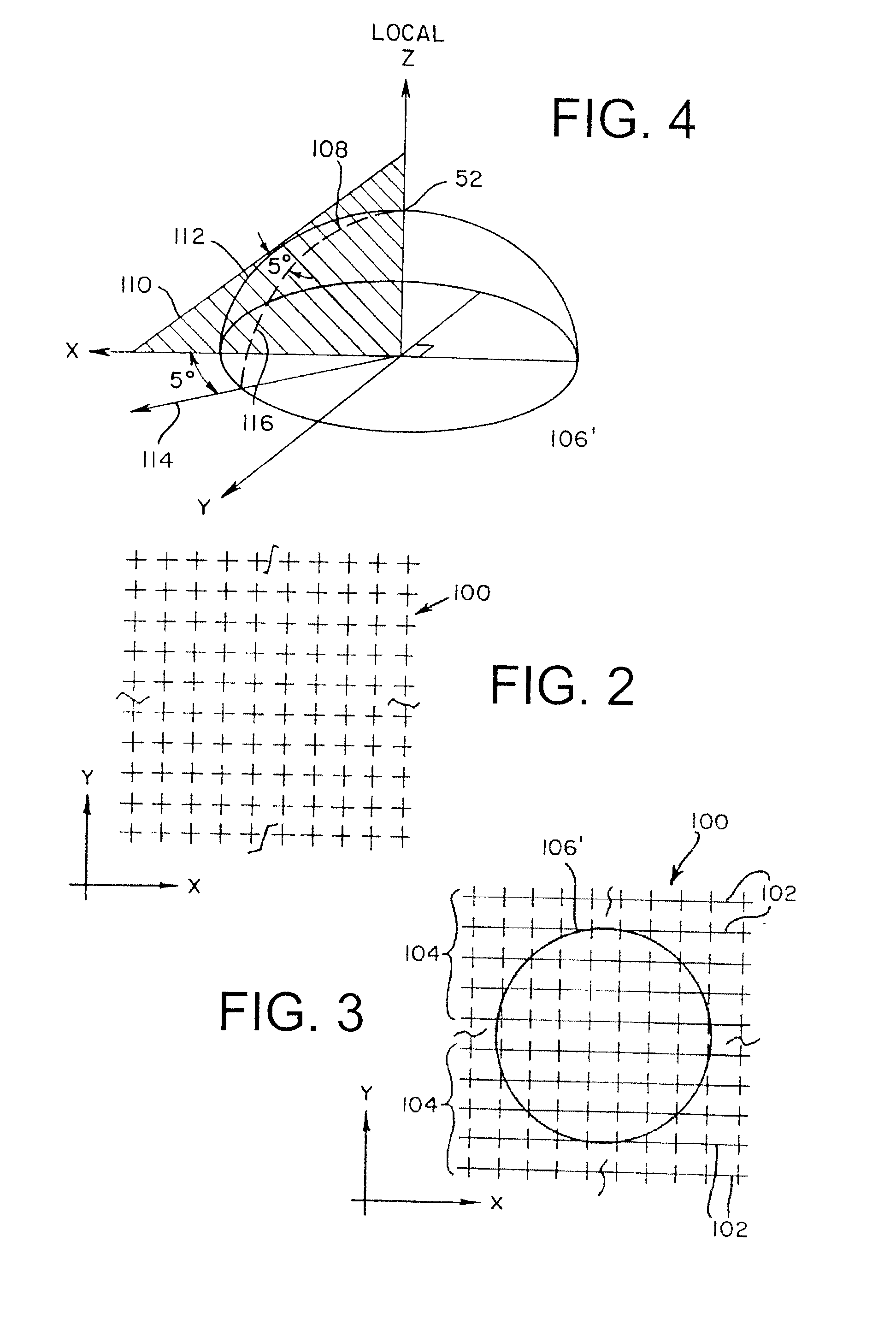
[0023]In conjunction with modern corneal procedures, such as corneal ablation surgery, for clinical applications, and for contact lens design and manufacture, high resolution cameras are used to obtain a digitized array of discrete data points on the corneal surface. One system and camera which have been available for mapping the cornea is the PAR Corneal Topography System (PAR CTS) of PAR Vision Systems. The PAR CTS maps the corneal surface topology in three-dimensional Cartesian space, i.e., along x- and y-coordinates as well as depth (Z) coordinate. Other systems that have worked successfully include the EyeShape system, provided by BioShape AG of Berlin, Germany and the Pentacam eye scanner, available from Oculus, Inc., of Lynnwood, Wash.

[0024]The “line-of-sight” is a straight line segment from a fixation point to the center of the entrance pupil. As described more fully in Mandell, “Locating the Corneal Sighting Center From Videokeratography,” J. Refractive Surgery, V. 11, pp. ...


PUM


Abstract

The carrier region extending beyond the optical portion of a contact lens overlying the cornea of an eye can be modeled in one universal shape that will fit all eyes. That shape is characterized by a curve of radius of curvature versus distance from the High point which is substantially linear with a first slope below a 10 mm diameter of the eye as projected onto a plane perpendicular to the optical axis, is substantially linear above 10 mm with a second slope which is substantially greater than the first slope, and which has an inflection point in the vicinity of approximately 10 mm. Preferably the first linear portion has a radius of curvature of approximately 7.6 mm at a diameter of about 7 mm, with a slope of about 0.13 (the first slope) and a radius of curvature of about 9 mm at a diameter of 12 mm, with a slope of about 0.45 (the second slope).

Description

BACKGROUND OF THE INVENTION[0001]The present invention relates generally to a method and apparatus for contact lens construction, and, more particularly concerns a method and apparatus for providing a universal construction for the non-optical peripheral area of a contact lens which rests on the eye, hereafter referred to as the “carrier.”[0002]Most common defects in human vision are caused by the inability of the eye to focus incoming light to a common focal point on the retina. For example, nearsightedness can be attributed to an eye which focuses light anterior to the retina, farsightedness can be attributed to an eye which focuses incoming light posterior to the retina, and astigmatism can be attributed to an eye which does not have a common focal point. Human optical scientists frequently model the cornea as a portion of an ellipsoid defined by orthogonal major and minor axes.[0003]Today, vision is commonly improved in one of two ways: either a lens is placed in front of the ey...

Claims


Application Information

Patent Timeline
IPC IPC(8): G02C7/04
CPCG02C7/047
Inventor LIEBERMAN, DAVID M.GRIERSON, JONATHAN
Owner SCI OPTICS INC
Why Eureka
Try Eureka