Image forming apparatus and method for controlling image forming apparatus
- Summary
- Abstract
- Description
- Claims
- Application Information
AI Technical Summary
Benefits of technology
Problems solved by technology
Method used
Image

Examples
embodiment 1
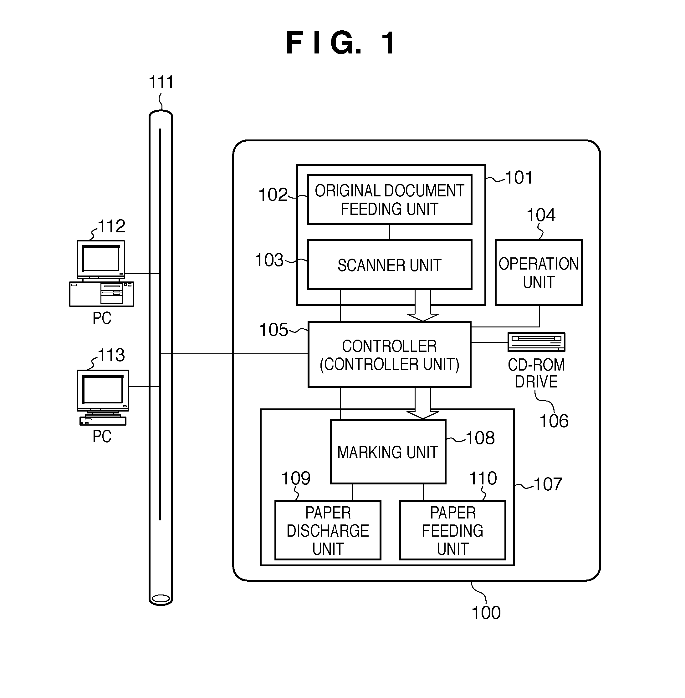
[0037]FIG. 1 is a diagram showing an overall configuration of an image forming system according to the present invention.
[0038]The image forming system includes a PC 112, a PC 113 and an image forming apparatus 100. These elements are connected via a network 111.
[0039]The image forming apparatus 100 includes a reader unit 101, an operation unit 104, a printer unit 107, and so on.
[0040]The reader unit (image input apparatus) 101 optically reads an image from an original document and converts the image to image data. The reader unit 101 includes a scanner unit 103 that has a function for reading an original document, and an original document feeding unit 102 that has a function for conveying the original document. A user can use the original document feeding unit 102 to cause an original document having a plurality of pages to be sequentially conveyed and read.
[0041]The printer unit (image output apparatus) 107 conveys a sheet (also referred to as a “print medium” or “recording paper”...
embodiment 2
Sequence for Outputting PDL Images
[0086]Embodiment 1 described sheet conveyance control performed when the image forming apparatus 100 executes a copy operation. In Embodiment 2, sheet conveyance control performed when an image forming apparatus 100 outputs images based on print data (PDL data) received from an external PC 112 or 113 will be described. The configuration of the image forming apparatus 100 is almost the same as that of Embodiment 1, so a detailed description thereof is omitted here.
[0087]FIG. 8 is a flowchart showing a procedure for outputting images based on print data (PDL data) received from the external PC 112 or 113. The processes shown in the flowchart of FIG. 8 are performed by the CPU 301 executing a program stored in the ROM 302.
[0088]First, in S901, the CPU 301 receives print data (print job) from the external PC 112 or 113. The received print data is stored in the HD 330.
[0089]In S902, the CPU 301 makes print settings based on print setting information incl...
embodiment 3
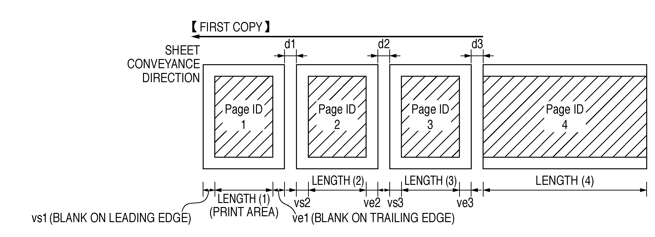
[0096]In Embodiment 1, an original document having a plurality of pages is automatically conveyed and read to generate image data, during which blank areas are detected from the original document. Then, the sheet conveyance interval at which the image data is transferred and printed onto a paper medium is changed based on blank area information. In the case where the user has requested to make two or more copies via the operation unit interface 327, the CPU 301 determines, after the first copy has been printed, the sheet conveyance interval based on blank information as shown in FIGS. 5A and 5B obtained through detection while reading and stored in the DRAM 304.
[0097]However, in the following cases, instead of detecting blank areas and storing the data to shorten the paper interval and applying the shortened paper interval to the second and subsequent copies, the shortened paper interval can be applied to the first and subsequent copies. For example, in the case where the reading sp...
PUM
 Abstract
Description
Claims
Application Information
 - Generate Ideas
- Intellectual Property
- Life Sciences
- Materials
- Tech Scout
- Unparalleled Data Quality
- Higher Quality Content
- 60% Fewer Hallucinations
Browse by: Latest US Patents, China's latest patents, Technical Efficacy Thesaurus, Application Domain, Technology Topic, Popular Technical Reports.
© 2025 PatSnap. All rights reserved.Legal|Privacy policy|Modern Slavery Act Transparency Statement|Sitemap|About US| Contact US: help@patsnap.com