Zoom lens barrel and image pickup apparatus having the same

a pickup apparatus and zoom lens technology, applied in the field of zoom barrels, can solve the problems of adverse effects of zoom operation, cam pins or cam groove wear, etc., and achieve the effect of reducing driving load and smooth zoom operation

Inactive Publication Date: 2011-02-17
CANON KK
View PDF3 Cites 6 Cited by
  • Summary
  • Abstract
  • Description
  • Claims
  • Application Information

AI Technical Summary

Benefits of technology

[0010]The present invention provides a lens barrel and an image pickup apparatus, which are capable of achieving a smooth zoom operation and reducing a driving load at the time of barrel retraction.

Problems solved by technology

However, the rectilinear guide grooves formed in this manner cause a fear that the cam pins of the lens retainer are disengaged from the cam grooves of the fixed cylinder at positions where the cam grooves are divided by the rectilinear guide grooves, or that the cam pins or the cam grooves are worn.
However, this lens barrel causes a fear that the cam pins are caught in cam groove entrances at the time of switching between the retracted region and the photographing region so that the zoom operation is adversely affected.

Method used


Image

  • Zoom lens barrel and image pickup apparatus having the same
  • Zoom lens barrel and image pickup apparatus having the same
  • Zoom lens barrel and image pickup apparatus having the same

Examples


Embodiment Construction

[0031]The present invention will now be described in detail below with reference to the drawings showing a preferred embodiment thereof.

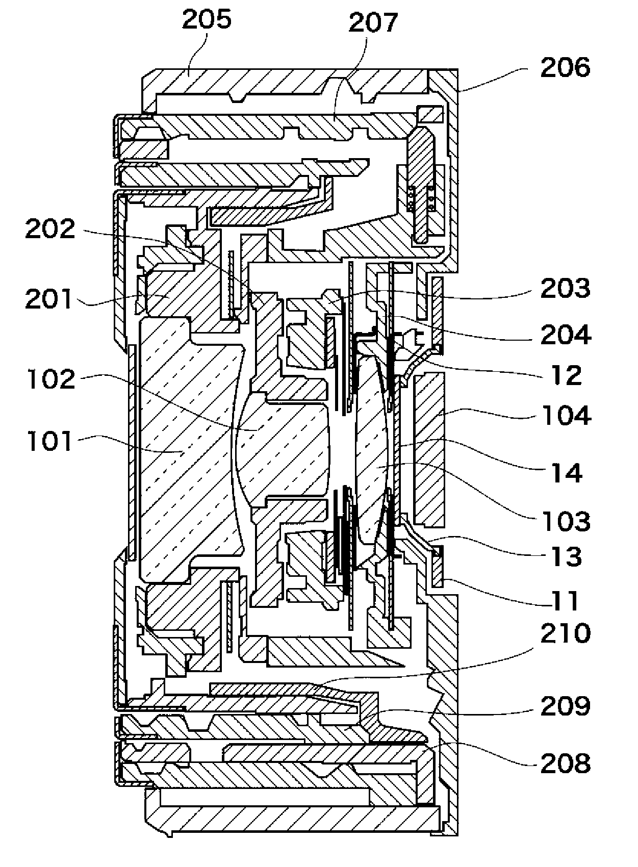
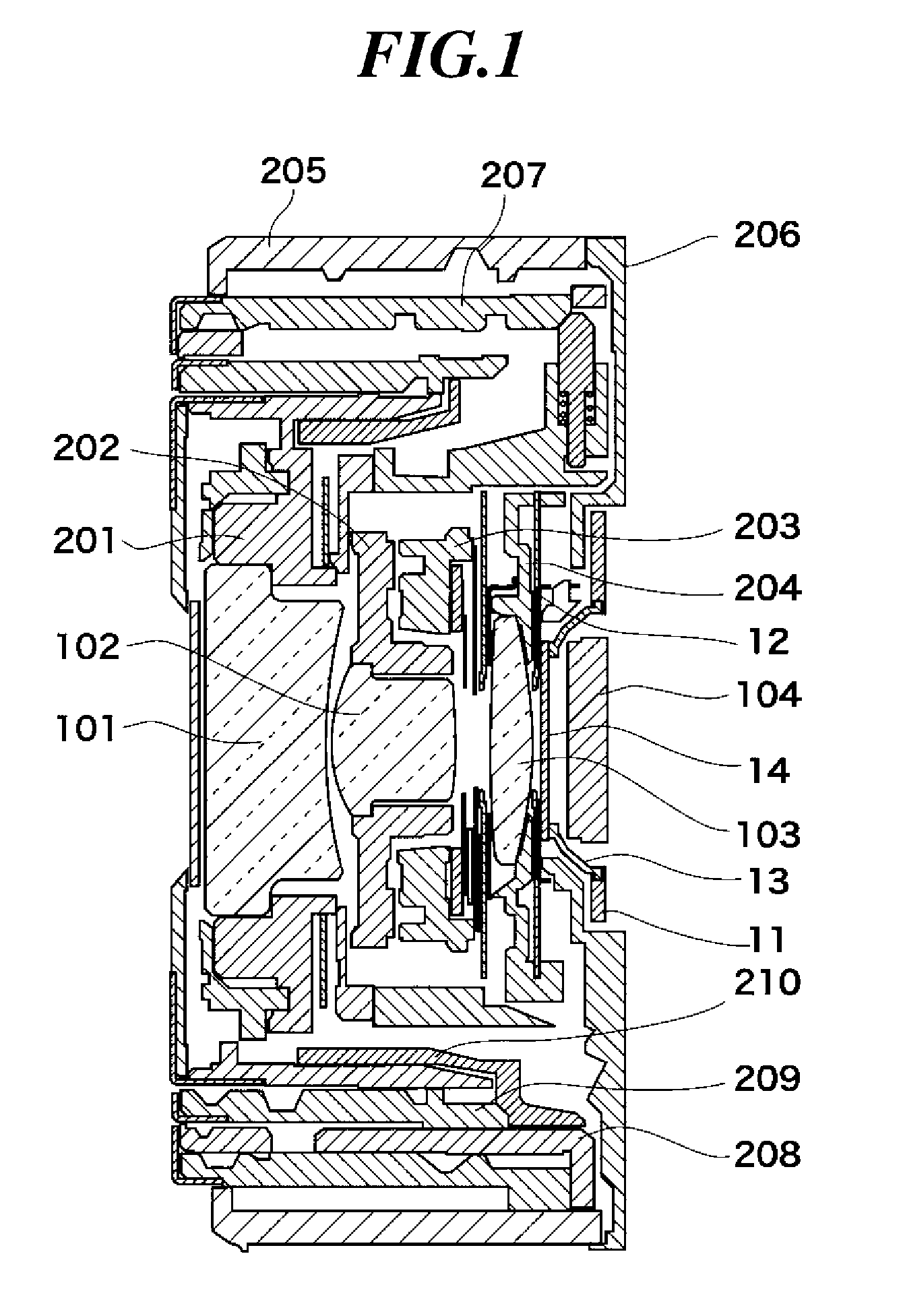
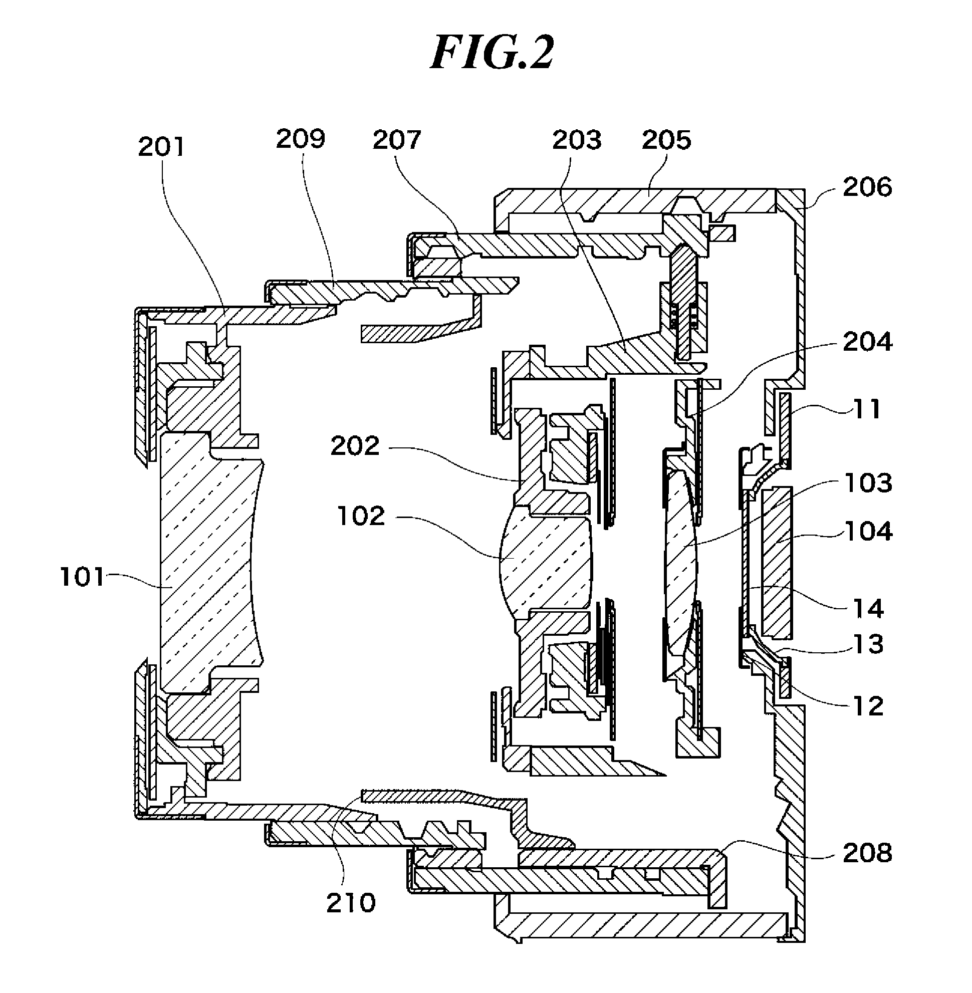
[0032]FIGS. 1 to 3 show in section view a lens barrel according to one embodiment of this invention in a retracted state, in a WIDE state, and in a TELE state, respectively.

[0033]FIG. 4 shows the lens barrel in exploded perspective view, and FIG. 5 shows in perspective view an assembly of a CCD holder and a third group barrel of the lens barrel.

[0034]The lens barrel of this embodiment is configured as a zoom lens barrel adapted to be mounted on an image pickup apparatus such as a digital camera. The lens barrel includes a first group barrel 201 that holds a first lens group 101, a second group unit (hereinafter, denoted by reference numerals 202, 203) including a second group holder 202 that holds a second lens group 102 and a second group base 203 that has an aperture and a shutter, and a third group barrel 204 that holds a third lens group 103.

[00...


PUM


Abstract

A lens barrel capable of achieving a smooth zoom operation and reducing a driving load at the time of barrel retraction. The lens barrel includes a rectilinear guide cylinder rectilinearly moving in an optical axis direction, and a movable cam cylinder moving in the optical axis direction while rotating relative to the guide cylinder. The guide cylinder is formed at its inner peripheral surface with a cam groove and a rectilinear guide groove that divides the cam groove at a boundary between a retracted region and a photographing region, and is formed with a penetration cam groove extending from the inner peripheral surface to an outer peripheral surface of the guide cylinder. The movable cam cylinder moves in the photographing region while the first pin engages the cam groove, and moves in the retracted region while the second pin engages the penetration cam groove.

Description

BACKGROUND OF THE INVENTION[0001]1. Field of the Invention[0002]The present invention relates to a lens barrel capable of zoom operation, and relates to an image pickup apparatus such as a digital camera having the lens barrel.[0003]2. Description of the Related Art[0004]Some conventional zoom lens barrel includes a fixed cylinder having an inner peripheral surface thereof formed with cam grooves, a cam cylinder having cam pins for engagement with the cam grooves of the fixed cylinder, and a lens retainer having cam pins for engagement with cam grooves formed on an inner peripheral surface of the cam cylinder. The cam cylinder moves along an optical axis direction while rotating. With rotation of the cam cylinder, the lens retainer relatively moves in the optical axis direction for zooming and retracting operations.[0005]With recent trend that image pickup apparatuses are made smaller in thickness and higher in magnification, the zoom lens barrel of the above construction has rectil...

Claims


Application Information

Patent Timeline
Patent Type & Authority Applications(United States)
IPC IPC(8): G02B15/14
CPCG02B7/10G03B17/04G03B9/26
Inventor FUKAI, YOSUKE
Owner CANON KK
Why Eureka
Try Eureka