Writing method for multilayer optical disc

Inactive Publication Date: 2011-02-17
QUANTA STORAGE INC
View PDF5 Cites 1 Cited by
  • Summary
  • Abstract
  • Description
  • Claims
  • Application Information

AI Technical Summary

Benefits of technology

[0008]One aspect of the invention is directed to a writing method for writing a multi-layer optical disc. Based on the optimum internal gains obtained when the objective lens are

Problems solved by technology

Since the reflection spots are very tiny, the electrical signals converted from the reflection spots are also very weak.
Consequently, writing on the optical disc is negatively

Method used


Image

  • Writing method for multilayer optical disc
  • Writing method for multilayer optical disc
  • Writing method for multilayer optical disc

Examples


first embodiment

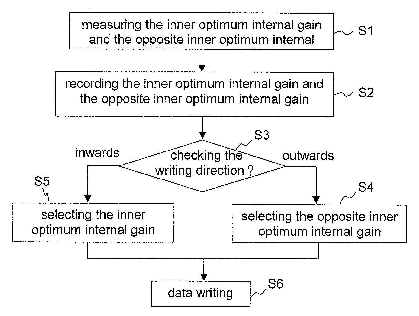
[0024]As indicated in FIG. 5, a flowchart of writing a multi-layer optical disc according to the invention is shown. Disclosed below are steps of measuring the inner optimum internal gain and the opposite inner optimum internal gain before writing data, to correct the offset of the tracking error signal. Firstly, at step S1, the optimum internal gains obtained when the objective lens is on the inner side and the opposite inner side of the pick-up head are respectively measured. Next, at step S2, the inner optimum internal gain and the opposite inner optimum internal gain are recorded. Then, at step S3, the writing direction of the optical disc is checked; and whether the objective lens is towards inner side or opposite inner side of the pick-up head is determined according to the specific writing direction on the optical disc. If the writing direction is outwards, at step S4, the opposite inner optimum internal gain is selected to generate a tracking error signal for locking and mov...

second embodiment

[0025]As indicated in FIG. 6, a flowchart of writing a multi-layer optical disc according to the invention is shown. Disclosed below are steps of measuring the inner optimum internal gain and the opposite inner optimum internal gain during writing data, to correct the offset of the tracking error signal. Firstly, at step R1, the DC level of the tracking error signal when the objective lens is located at the center of the pick-up head is measured and used as a reference level TEr for the offset of the tracking error signal. Next, at step R2, the objective lens is moved off the center of the pick-up head and towards one inner side of the pick-up head and is aligned to the data track. Then, at step R3, the DC level of the tracking error signal is measured based on the pre-determined negative internal gain, and the measured DC level of the tracking error signal is deducted by the reference level TEr to obtain an offset TEofsn of the tracking error signal under negative internal gain. At...


PUM


Abstract

A writing method for a multilayer optical disc. The method includes: measuring and recording optimum internal gains obtained when the objective lens is located on each inner side of the pick-up head, respectively, checking the writing direction based on the specific writing direction on each data layer of the disc, selecting the inner optimum internal gain when the writing direction is toward outside, and selecting the opposite inner optimum internal gain when the writing direction is toward inside to minimize the offset of the tracking error signal.

Description

[0001]This application claims the benefit of Taiwan application Serial No. 98127668, filed Aug. 17, 2009, the subject matter of which is incorporated herein by reference.BACKGROUND OF THE INVENTION[0002]1. Field of the Invention[0003]The invention relates in general to an optical disc drive, and more particularly to an optical disc drive which writes data on data layers in a multi-layer optical disc along different writing directions.[0004]2. Description of the Related Art[0005]Optical disc drive emits micro spots whose diameter range 0.85˜2.11 μm on an optical disc, and accordingly receives a reflection light from the optical disc. The electrical signal, formed by the difference in the amount of the reflection light, further controls the optical disc drive to read data along the data tracks on the optical disc. Since the reflection spots are very tiny, the electrical signals converted from the reflection spots are also very weak. To stably control the tracking to improve writing qu...

Claims


Application Information

Patent Timeline
IPC IPC(8): G11B7/20
CPCG11B7/0903G11B2007/0013G11B7/0941G11B7/094
Inventor HUANG, CHAO-CHUNCHEN, SONG-RUI
Owner QUANTA STORAGE INC
Why Eureka
Try Eureka