
Device and method to control an electron beam for the generation of x-ray radiation, in an x-ray tube

Active Publication Date: 2011-02-17
SIEMENS HEALTHCARE GMBH
View PDF13 Cites 13 Cited by
  • Summary
  • Abstract
  • Description
  • Claims
  • Application Information

AI Technical Summary

Benefits of technology

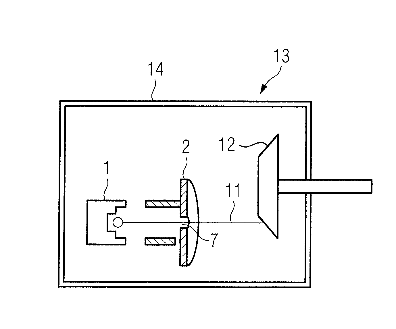
[0016]According to one variant of the invention, the diaphragm has an aperture to pass the electron beam. Such an aperture diaphragm in particular enables fast blocking of the electron beam. While the electron beam passes unhindered through the opening of the diaphragm and strikes an x-ray target (anode) to generate x-ray radiation, this can be deflected quickly onto the diaphragm (and thus be blocked) by switching of the voltage at the control element, such that the generation of x-ray radiation is also suppressed.
[0019]According to a further variant of the invention, the magnitude of the first voltage is smaller and the magnitude of the second voltage is larger than the magnitude of the emitter voltage, so blocking and unblocking of the electron beam are possible.

Problems solved by technology

A problem with the technique of varying the heating power, due to the thermal inertia, for example with regard to the aforementioned example pertaining to a computed tomography apparatus with two x-ray systems is to suppress the emission of x-ray radiation by the x-ray source of the other x-ray system during the short readout of measurement data of the x-ray detector of the one x-ray system, and to immediately apply x-ray radiation with the x-ray source of the other x-ray system again after the readout.

Method used


Image

  • Device and method to control an electron beam for the generation of x-ray radiation, in an x-ray tube
  • Device and method to control an electron beam for the generation of x-ray radiation, in an x-ray tube
  • Device and method to control an electron beam for the generation of x-ray radiation, in an x-ray tube

Examples


Embodiment Construction

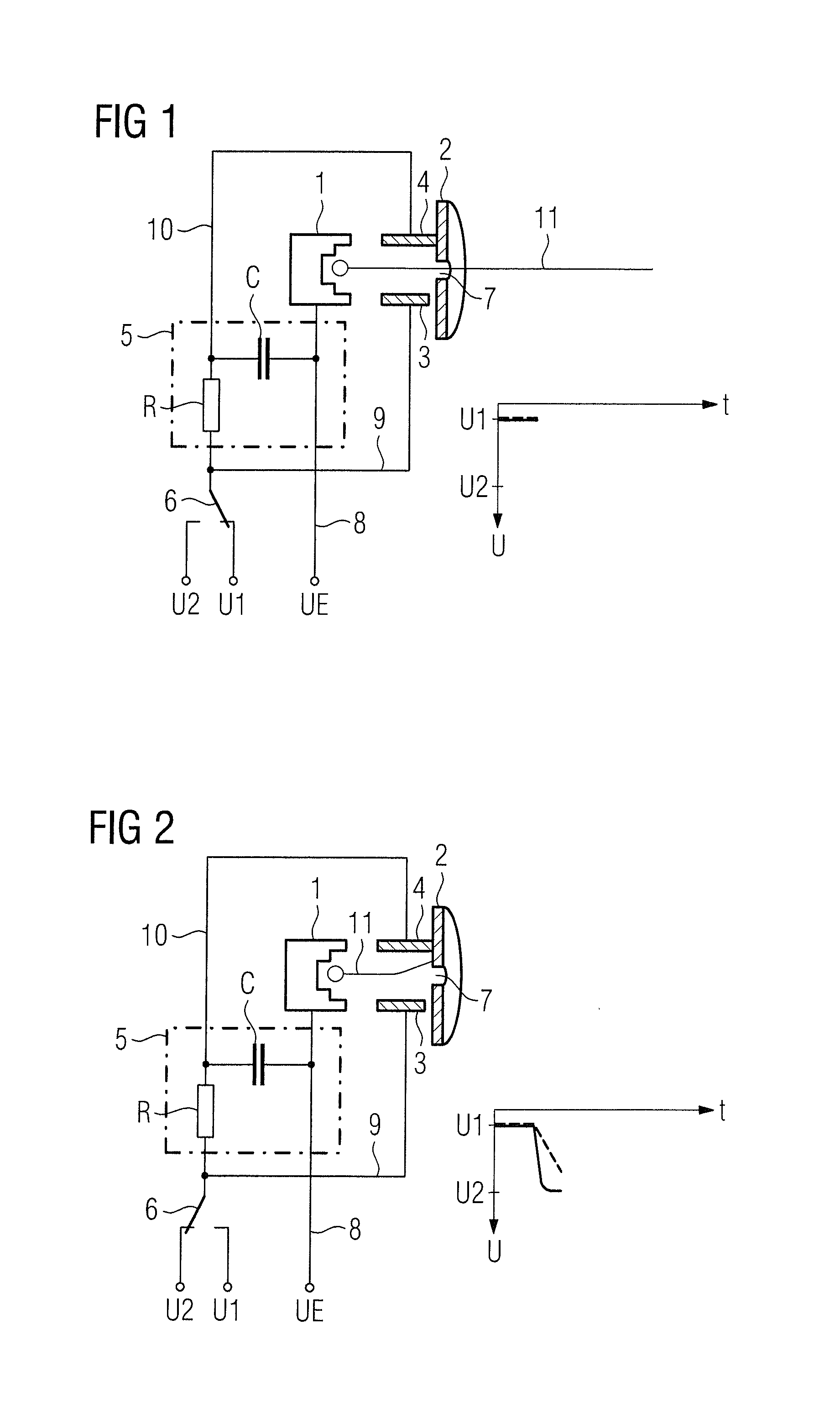
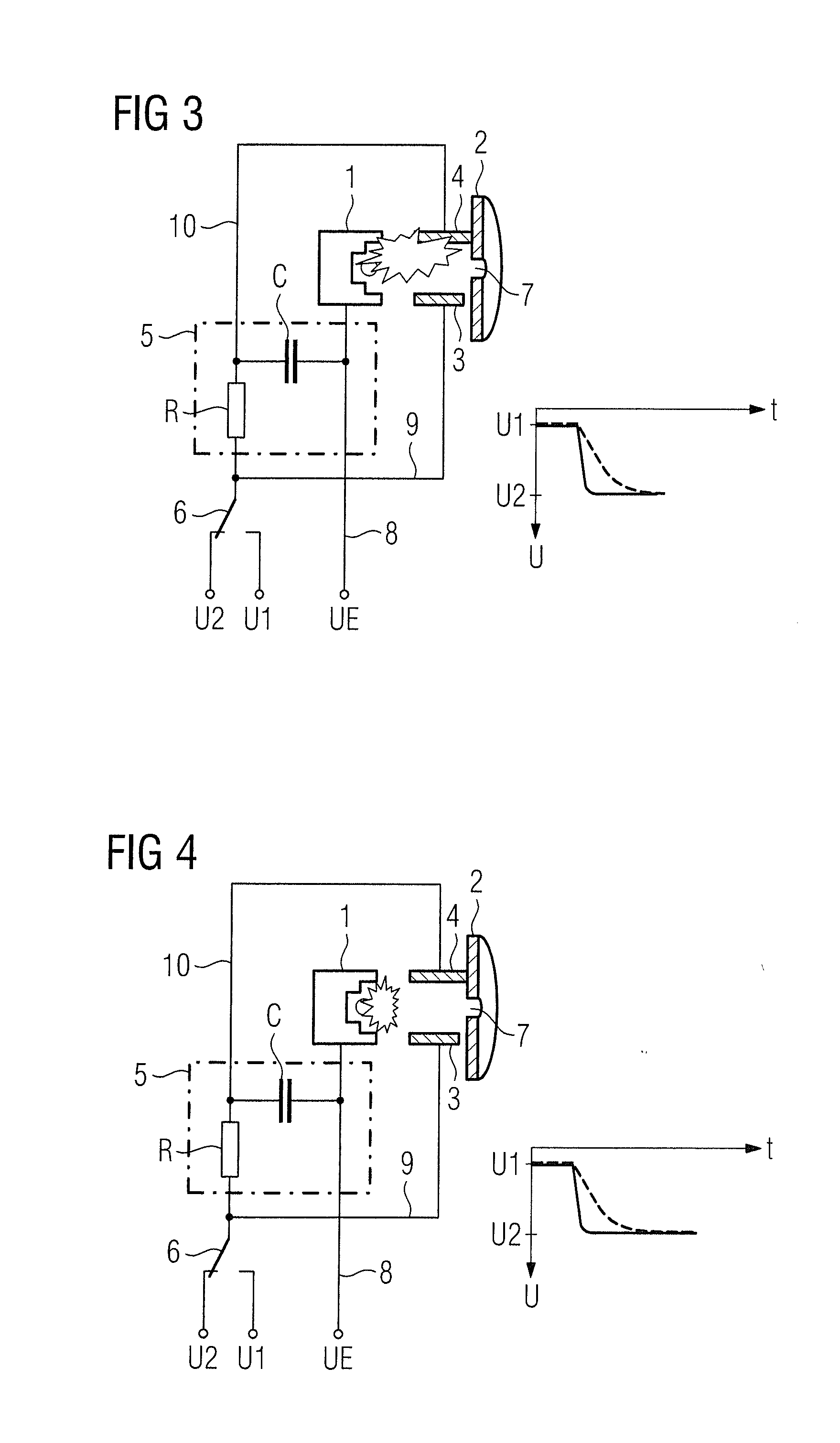
[0024]A device according to the invention to generate and control an electron beam for the generation of x-ray radiation is shown in FIG. 1. The device has an electron emitter 1, a diaphragm 2 arranged between the electron emitter 1 and an anode (not shown in FIG. 1), two electrodes 3 and 4, an electrical circuit 5 and a switching arrangement in the form of a switch 6.

[0025]In the exemplary embodiment of the invention, the diaphragm 2 is a disc-shaped aperture diaphragm 2 with an aperture 7. In the case of the present exemplary embodiment of the invention, the aperture diaphragm 2 is electrically connected with the electrode 4.

[0026]In the exemplary embodiment of the invention, the electron emitter 1 (which, in the case of the present exemplary embodiment of the invention, is a field emitter, thus an emitter that emits electrons as a result of an electrical field) is connected with a feed line 8 to a voltage of UE=−120 kV that decreases between the electron emitter 1 and the anode. ...


PUM


Abstract

A device to control an electron beam for the generation of x-ray radiation, has an electron emitter to generate an electron beam, to which emitter an emitter voltage can be applied, a diaphragm, at least two control elements associated with the diaphragm to affect the electron beam, and switching arrangement with which at least two different electrical voltages can be applied to the at least two control elements. The same electrical voltage is applied to each of the at least two control elements. Upon switching the voltage, an electrical circuit that delays the setting of the respective voltage at the one control element is associated with the connection line of the one control element with the switching arrangement to switch over the voltage. The invention moreover concerns an operating method for the device and an x-ray tube provided with the device.

Description

BACKGROUND OF THE INVENTION[0001]1. Field of the Invention[0002]The present invention concerns a device and a method to control an electron beam emanating from an emitter of electrons for the generation of x-ray radiation, in particular for the modulation of x-ray radiation. The invention moreover concerns an x-ray tube having such a device.[0003]2. Description of the Prior Art[0004]In the use of x-ray radiation for imaging in medical engineering, there are various application cases in which modulation of the x-ray radiation or the radiation power within different time periods is desirable. For example, in x-ray computed tomography, particularly in the acquisition of 2D x-ray projections of measurement subjects that are not rotationally symmetrical, the x-ray radiation is matched to the respective body cross section that is to be exposed.[0005]A further application case for modulation of x-ray radiation in x-ray computed tomography is in computed tomography apparatuses with two x-ra...

Claims


Application Information

Patent Timeline
IPC IPC(8): H01J35/14
CPCH01J35/045H05G1/38H01J35/14H01J35/147
Inventor GRASRUCK, MICHAELSCHALLER, ANDREAS
Owner SIEMENS HEALTHCARE GMBH
Learn More