Turbine housing with wall cladding

a technology of wall cladding and turbine housing, which is applied in the direction of machines/engines, stators, liquid fuel engines, etc., can solve the problems of leakage in the joint area and leakage herewith, and achieve the effect of simple sealing of the joints, improved performance and improved sealing

Inactive Publication Date: 2011-02-17
SIEMENS AG
View PDF2 Cites 4 Cited by
  • Summary
  • Abstract
  • Description
  • Claims
  • Application Information

AI Technical Summary

Benefits of technology

[0006]An object of the invention is to achieve a sealing of the joi

Problems solved by technology

In the region of the joints, leakages frequently occur during operation of the turbine, so that in the case of a steam turbine, hot steam can escape outwards through the joint.
The leakages herewith occur particularly between adjacent chambers of the

Method used


Image

  • Turbine housing with wall cladding
  • Turbine housing with wall cladding
  • Turbine housing with wall cladding

Examples


Embodiment Construction

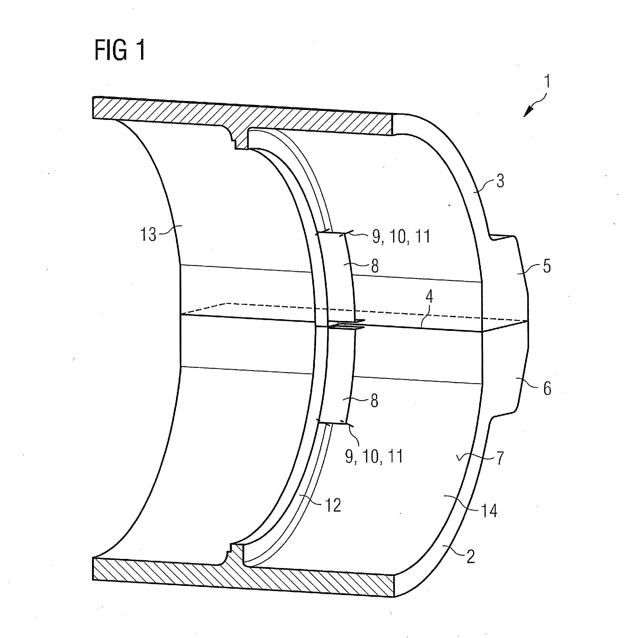
[0019]The figures illustrate very simplified representations in each instance, in which only the essential components needed to describe the invention are shown. Identical and / or functionally identical components are provided with the same reference characters throughout all the figures.

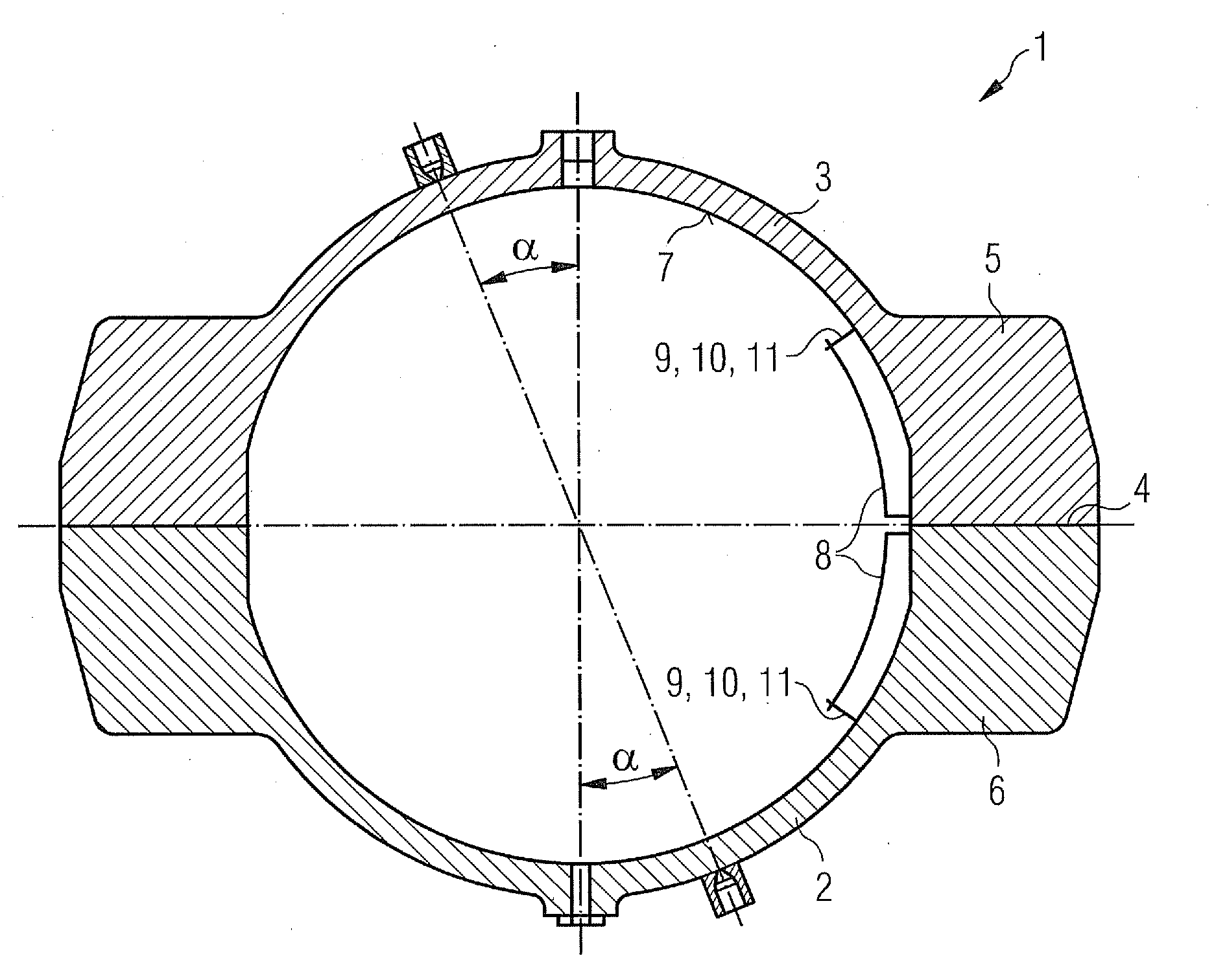
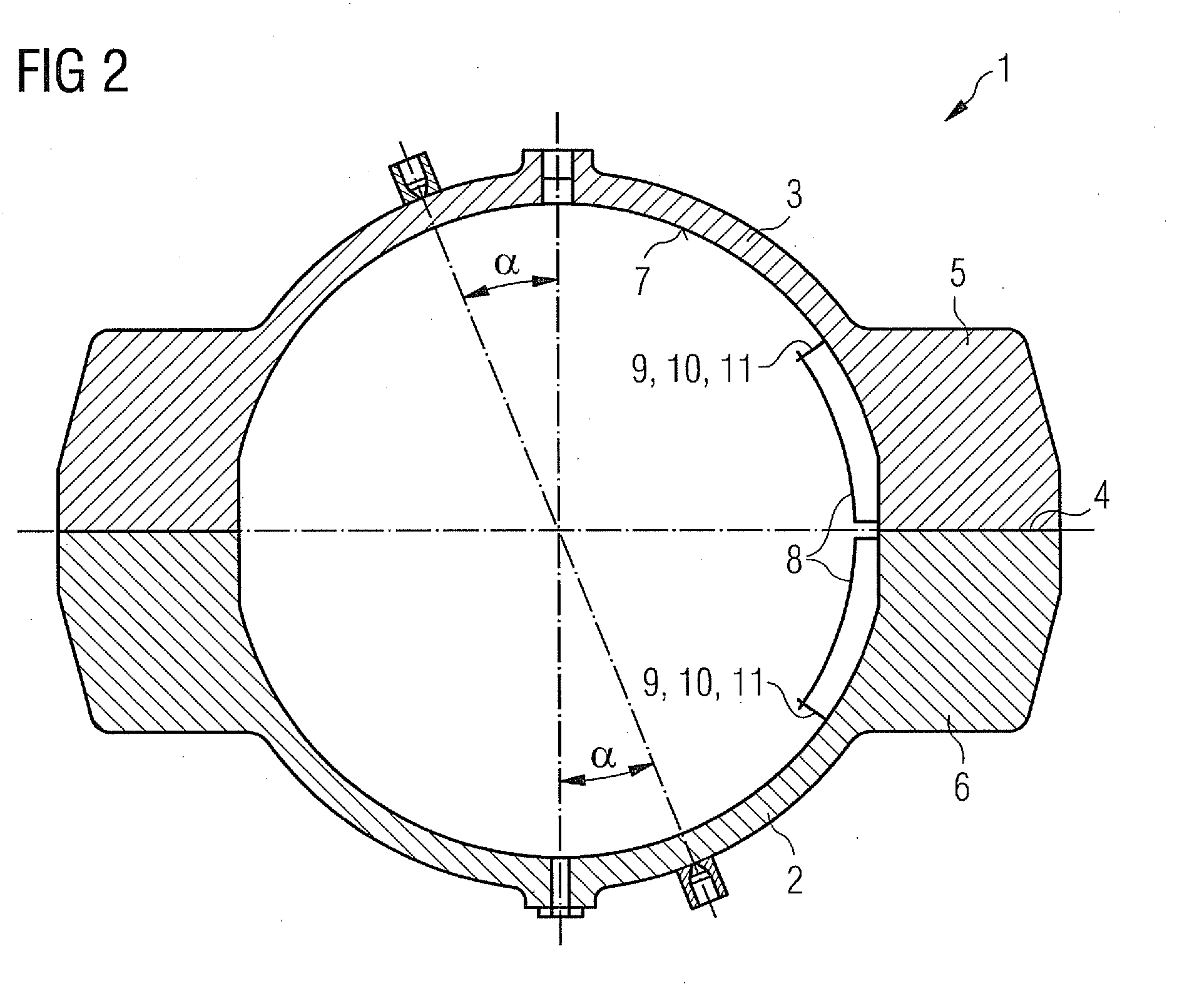
[0020]FIG. 1 shows a three-dimensional section through an inventive turbine housing. The turbine housing 1 includes a turbine housing lower part 2 and a turbine housing upper part 3. The two turbine housing parts 2, 3 are joined to one another in the assembled state. Joints 4 thereby form on the joining areas in each instance. To ensure that no fluid can escape outwards from the interior of the turbine housing 1, the joints 4 must be closed in as tight a fashion as possible. To this end, the turbine housing lower part 2 and the turbine housing upper part 3 are fixedly screwed to one another. To enable a good screwing connection between the two turbine housings 2 and 3, both turbine housing parts comp...


PUM


Abstract

A turbine housing for a turbine is provided. The turbine housing includes a wall cladding on an inner wall of the turbine housing. In a region of joint flanges, the wall cladding is arranged and embodied such that the wall cladding reduces convective heat transfer and thermal radiation in a region of the joint flanges.

Description

CROSS REFERENCE TO RELATED APPLICATIONS[0001]This application claims priority of German Patent Application No. 10 2009 037 413.2 DE filed Aug. 13, 2009, which is incorporated by reference herein in its entirety.FIELD OF INVENTION[0002]The invention relates to a turbine housing, in particular a steam turbine, which consists of a turbine housing lower part and a turbine housing upper part, which are joined together in the assembled state and in this way each embody a joint at their joining areas, with each turbine housing part comprising a joint flange in the region of the joint, by way of which the turbine housing parts are screwed to one another by means of joint screws.BACKGROUND OF INVENTION[0003]The exterior housings of turbine housings are usually embodied in two parts and include a turbine housing lower part and a turbine housing upper part. The two part embodiment of the turbine housing facilitates assembly of the rotor. The turbine housing lower part and the turbine housing u...

Claims


Application Information

Patent Timeline
IPC IPC(8): F01D1/02
CPCF01D25/145
Inventor LOCHNER, KLAUSSTRAUCH, MATTHIAS
Owner SIEMENS AG
Why Eureka
Try Eureka