Multi-stage compressor

a compressor and multi-stage technology, applied in the direction of machines/engines, liquid fuel engines, positive displacement liquid engines, etc., can solve the problems of less energy required for gas pumping, small operating window, and worse energy efficiency, so as to increase the capacity and reduce the capacity

Inactive Publication Date: 2011-02-17
DANFOSS AS
View PDF6 Cites 48 Cited by
  • Summary
  • Abstract
  • Description
  • Claims
  • Application Information

AI Technical Summary

Benefits of technology

[0009]There is further provided a method for adjusting the capacity of a multi-stage compressor comprising a rotating shaft and a primary pumping circuit comprising at least one primary stage coupled to the rotating shaft, comprising determining current capacity requirements of the multi-stage compressor; coupling at least one secondary stage to the rotating shaft to increase the capacity, and decoupling at least one of the at least one secondary stage from the rotating shaft to decrease the capacity, as determined by the previous step.
[0010]There is further provided a coupling assembling for coupling a secondary stage to a rotating shaft of a compressor comprising a primary stage, comprising a permanent magnet inserted into either one of the end of the rotating shaft or the secondary impeller and a magnetic piece inserted into the remaining one of the secondary impeller or the end of the rotating shaft, the secondary stage being held onto the rotating shaft by magnetic forces between the permanent magnet and the magnetic piece.
[0011]There is further provided a coupling assembly for coupling a secondary impeller to a rotating shaft of a compressor comprising a primary stage, comprising a first magnet inserted in the rotating shaft; and a second magnet inserted in the secondary impeller, the secondary impeller attaching itself to the rotating shaft by the attraction strength between opposing poles of the first and second magnets.

Problems solved by technology

Moreover, the higher the pressure ratio, the less flexible the compressor becomes in its ability to unload, resulting in a smaller operating window and in more energy being required to pump the gas.
When conditions change, a compressor must then operate at “off design” in a very wide range of conditions, resulting generally in worse energy efficiency.
Although typically more efficient than other forms of compressors, centrifugal compressors are also less flexible in simultaneously handling high-pressure ratios and low capacity demand.
While this method of pumping can allow high-pressure ratios, it also limits the ability for the compressors to unload without going into a condition known as surge.
Another difficulty in designing a multi-stage compressor is to design it so that it may handle high pressure ratios while having a required turndown minimum capability.

Method used


Image

  • Multi-stage compressor
  • Multi-stage compressor
  • Multi-stage compressor

Examples


Embodiment Construction

[0027]The present invention is illustrated in further details by the following non-limiting examples.

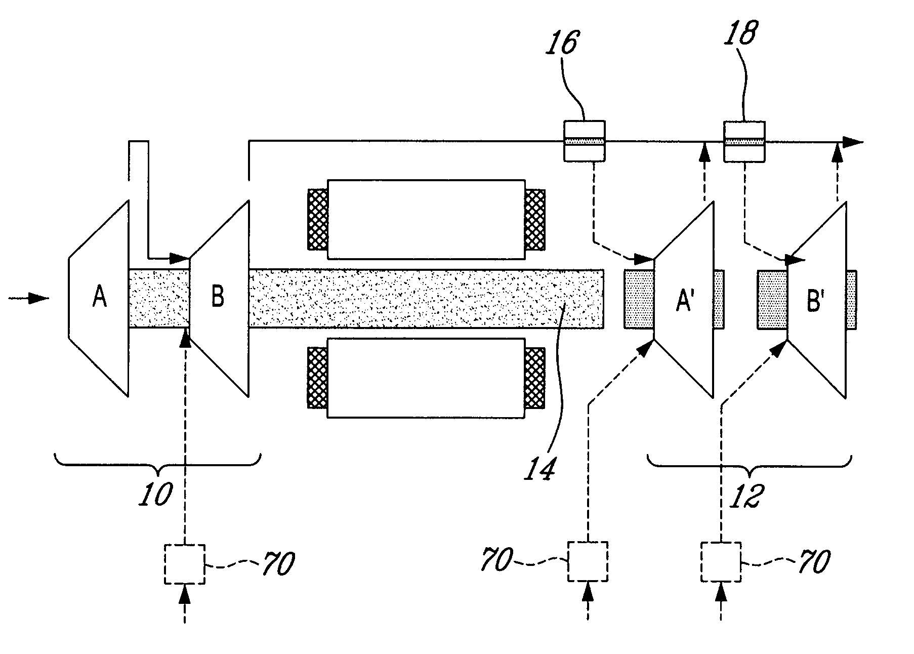
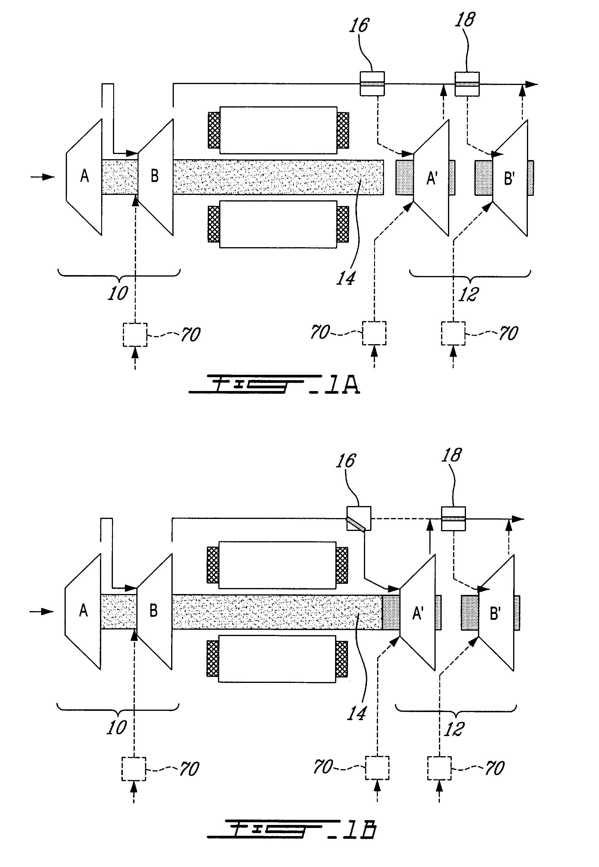
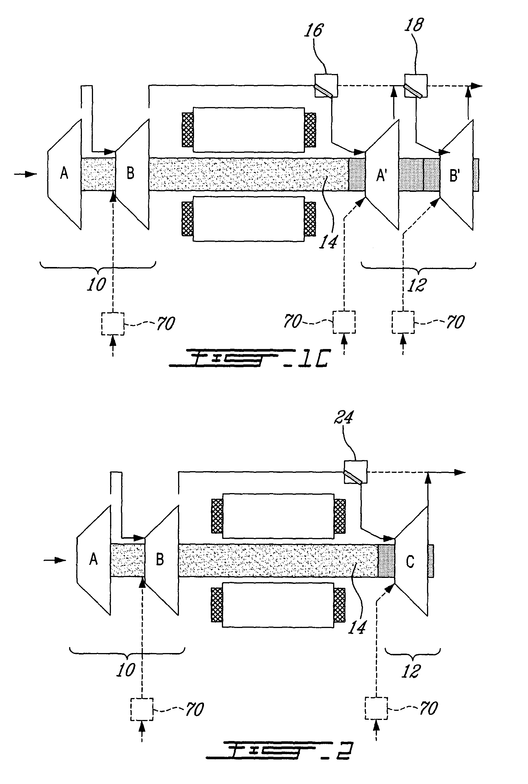
[0028]There is generally provided a system and a method for adding and subtracting stages of compression to a compressor as, and when, the compressor requires them.

[0029]For example, if the compressor needs only a low pressure ratio, then the system and method allow the compressor to operate with only a primary pumping circuit spinning, while available additional stages, forming a secondary pumping circuit, and which may be required at other times when the required pressure ratios increase, being decoupled from the rotating shaft, so that the compressor only pumps at its most efficient and flexible point.

[0030]On the contrary, when a higher pressure ratio is required, such as when outside ambient temperatures increase in the middle of summer in an air-conditioning installation for example, since the additional stages are required in order to reach higher pressure ratios, the system a...


PUM


Abstract

A system and a method for adding and subtracting stages of compression to a compressor as and when the compressor requires them. If the compressor needs only a low pressure ratio, then the system and method allow the compressor to operate with only a primary pumping circuit spinning, while available additional stages, forming a secondary pumping circuit, and which may be required at other times when the needed pressure ratios increase, are decoupled from the rotating shaft, so that the compressor pumps at its most efficient and flexible point. Further, a system and method for adding and subtracting stages of compression to a compressor in order to increase and decrease the pumping capacity as and when required to satisfy a given load requirement.

Description

FIELD OF THE INVENTION[0001]The present invention relates to multi-stage compressors. More specifically, the present invention is concerned with multi-stage compressors of variable pumping capacity and pressure ratios.BACKGROUND OF THE INVENTION[0002]Compressors used in most industries are often required to vary both their pumping capacity and their pressure ratios. In the particular instance of the air conditioning and refrigeration industries, cooling or heating loads vary throughout the year for example, and the required pressure ratios vary accordingly as the condensing temperatures and evaporating temperatures vary. Typically, as the outside ambient temperature rises, so do the required pressure ratio and the required capacity. Moreover, the higher the pressure ratio, the less flexible the compressor becomes in its ability to unload, resulting in a smaller operating window and in more energy being required to pump the gas.[0003]Traditionally, centrifugal compressors are designe...

Claims


Application Information

Patent Timeline
Patent Type & Authority Applications(United States)
IPC IPC(8): F04B25/00F03G7/00
CPCF04D17/14F04D27/0269F04D27/02F04D25/02F04D29/052
Inventor CONRY, RONALD DAVIDVESTERGAARD JOERGENSEN, HENRIKLOPES ALVARES, JR., JOSE
Owner DANFOSS AS
Why Eureka
Try Eureka