
Wearable Chemical Dispenser

a dispenser and chemical technology, applied in the field of wearable devices, can solve the problems of reducing the efficiency of chemical consumption, so as to achieve the effect of reducing the cost of chemical consumption, and reducing the waste of actives

Active Publication Date: 2011-02-17
SC JOHNSON & SON INC
View PDF23 Cites 29 Cited by
  • Summary
  • Abstract
  • Description
  • Claims
  • Application Information

AI Technical Summary

Benefits of technology

[0024]In other preferred forms the housing has a plurality of spaced apart openings, the openings being spaced around at least 180 degrees (more preferably at least 235 degrees) of a side structure of the housing, and a plurality of the blades are substantially perpendicular to a front wall of the housing, the front wall of the housing having an array of inlet apertures. The device can produce an average volumetric flow rate of air of at least 1.5 cubic feet per minute over a twelve hour period (preferably for an even longer period), yet is so efficient in energy use and power requirements more compact batteries (e.g. AAA rather than AA) can be used to power the device. This not only makes the device more compact from that factor, this permits the batteries to be positioned in an otherwise unavailable location, thereby further reducing the size and weight of the device.
[0042]Hence, it should be appreciated that the devices of the present invention have more efficient power usage, thereby permitting smaller power supplies and in any event a more compact and more lightweight assembly. Further, these devices make it more comfortable for the device to be operated even when the consumer is sitting and also provide greater control of the dispensing direction. Also, the special hinging and notch arrangement holds the lid open during replacement of the refill of active, but will cause the lid to snap to the closed once the lid is moved to a defined midpoint. This facilitates refill replacement.
[0043]These improvements lower the cost of production, permit the device to be operated at lower cost, and meets consumer preferences to minimize the weight of the device if a device like this is to be used.

Problems solved by technology

However, some consumers have expressed a reluctance to apply insect repellents directly to their skin or to delicate clothing.
However, some such devices may blow the active too far out away from the human body, causing too little of the active to reach locations of primary concern (e.g. near ankles).
Other such devices do not provide a way of minimizing waste of the active, such as while blower operation is suspended between uses.
Still other such devices are unduly costly, are too heavy, or have other deficiencies.

Method used


Image

  • Wearable Chemical Dispenser
  • Wearable Chemical Dispenser
  • Wearable Chemical Dispenser

Examples


Embodiment Construction

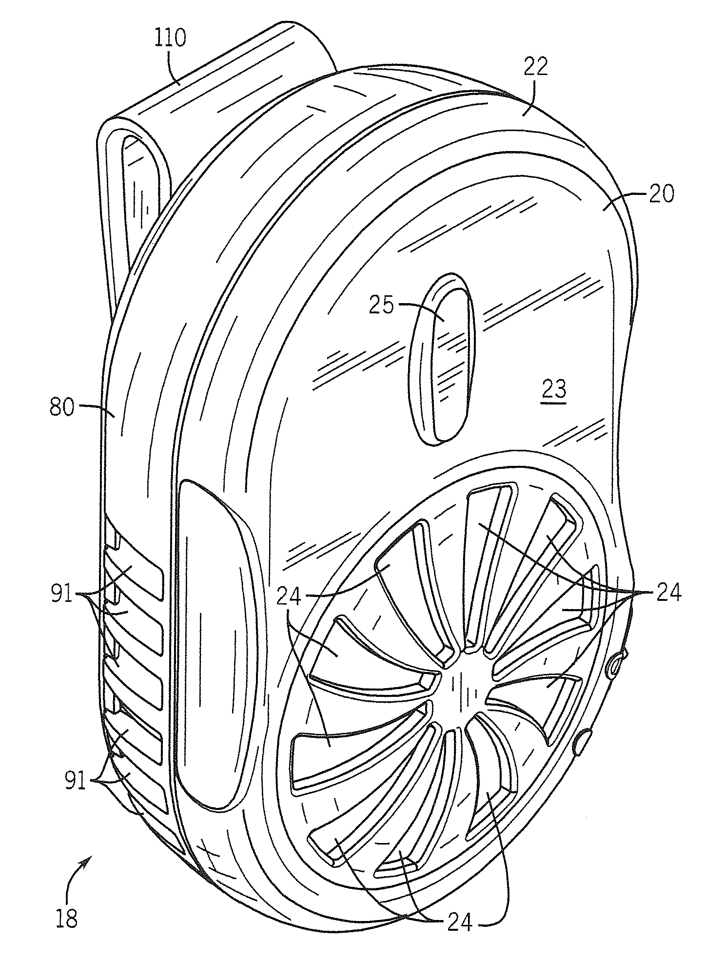
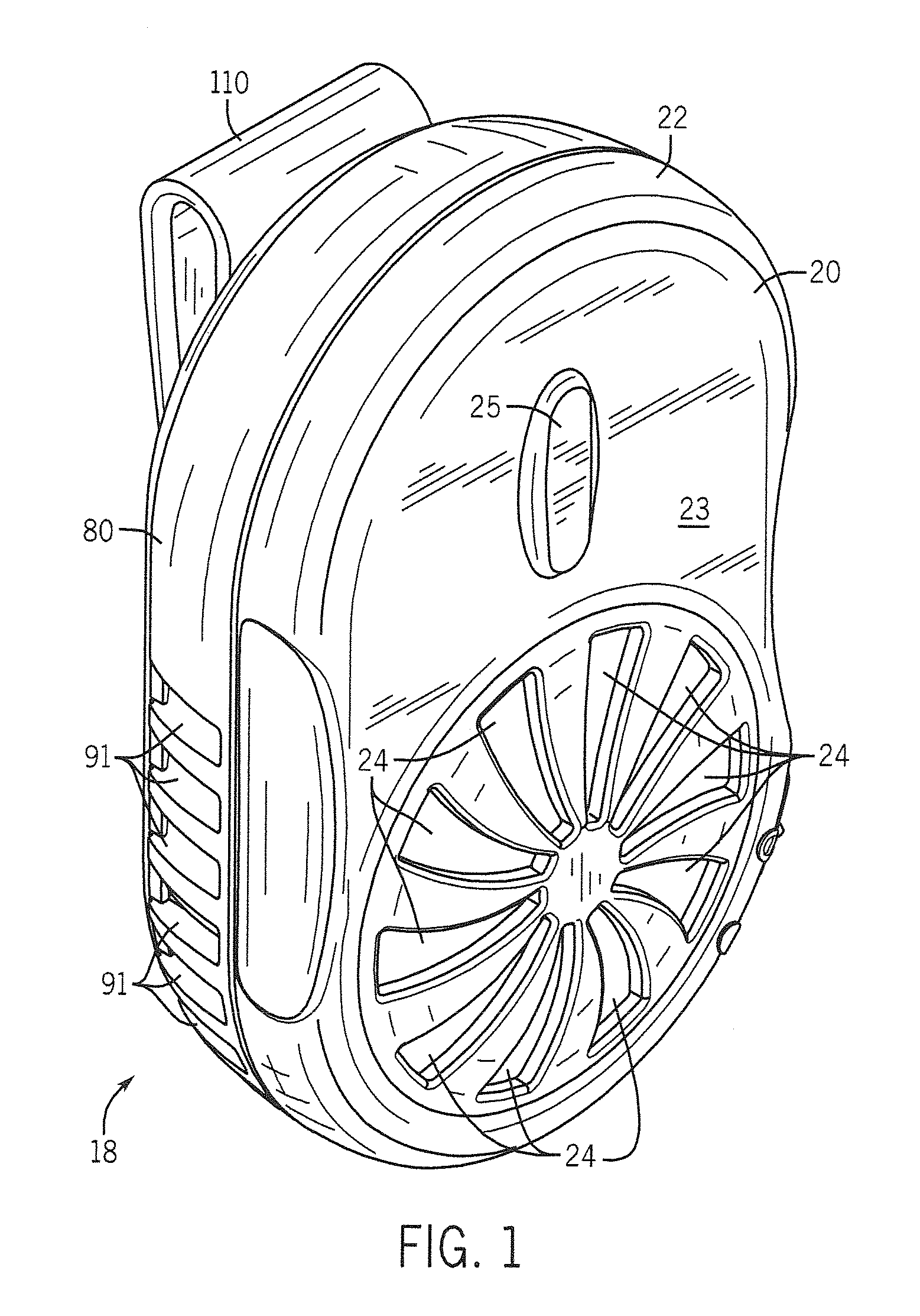
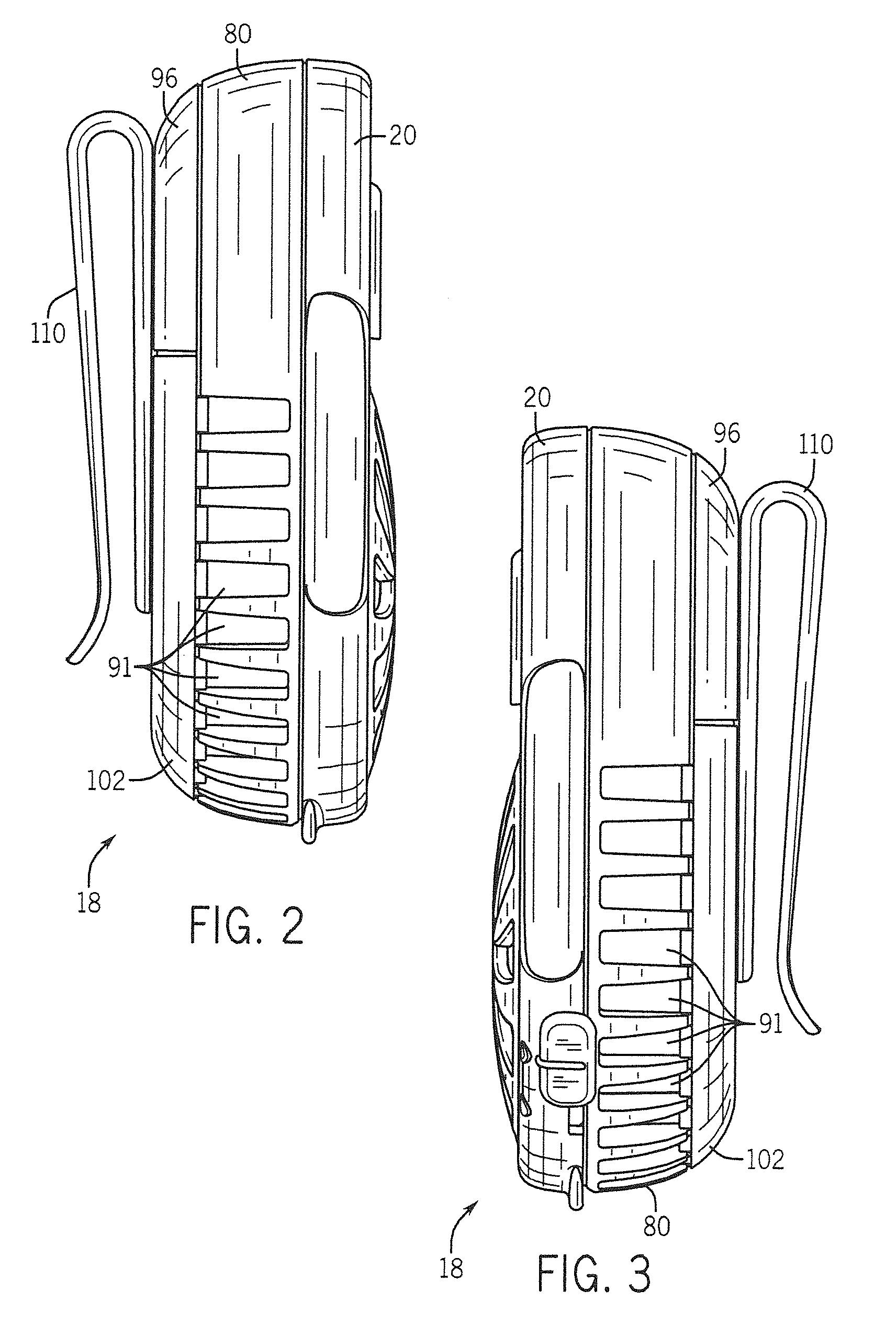
[0059]A preferred example wearable chemical dispenser 18 is shown in FIGS. 1-11. The wearable chemical dispenser 18 includes a top housing section 20 having a generally oblong side wall 22 that extends from a top wall 23. In use, the wall 23 is typically frontally disposed and acts as a lid. A plurality of spaced apart apertures 24 are radially arranged in the top wall 23 of the top housing section 20. The apertures 24 provide an inlet for permitting air to enter into an interior space of the wearable chemical dispenser 18. A tab 26 provides a means to grasp the top housing section 20 when opening the top housing section 20.

[0060]The wearable chemical dispenser 18 also includes a slide cover 28 having an on-off button 29, openings 31, and a cam projection 32. A fastener 34 (see FIG. 6) mounts the slide cover 28 to the top housing section 20 such that the slide cover 28 may rotate with respect to the top housing section 20 when a user moves the on-off button 29 along the side wall 22...


PUM


Abstract

Wearable devices for dispensing insect repellents, fragrances, and / or other chemicals along the outside of the clothing of a human are disclosed. They are of the type that are clipped onto a belt or the like, and use a powered fan to dispense active. They are configured with fan rotor arrangements to minimize power use while still achieving acceptable air flow rates. These changes permit use of smaller batteries and more compact arrangements for battery positioning. This in turn permits a much more compact and lightweight construction to achieve the desired results. The devices are also provided with a rotatable clip structure to render use of the device more comfortable when the user is seated and to provide greater control over the direction of the dispensing. Further, they are provided with modified lids to facilitate active refill replacement.

Description

CROSS-REFERENCES TO RELATED APPLICATIONS[0001]Not Applicable.STATEMENT REGARDING FEDERALLY SPONSORED RESEARCH[0002]Not Applicable.BACKGROUND OF THE INVENTION[0003]The present invention relates to wearable devices that dispense chemicals such as insect repellents and / or fragrances.[0004]Various techniques have been developed to provide humans with protection from insect bites. For insect control inside buildings a primary emphasis is placed on trying to keep insects from entering the building at all (e.g. placing screens over windows). This sometimes is supplemented with chemical treatment of room air and / or the use of traps. See e.g. U.S. Pat. Nos. 6,582,714 and 7,175,815, and also U.S. Patent Application Publication Nos. 2005 / 0079113, 2006 / 0039835, 2006 / 0137241 and 2007 / 0036688.[0005]When the individual is outdoors where the area cannot be effectively screened, and the individual is mostly staying in a particular area (e.g. at a picnic, or on a patio near a building), traps and are...

Claims


Application Information

Patent Timeline
IPC IPC(8): A61L9/00
CPCA01M1/2033A01M1/2055A61L2209/133A61L9/122A01M29/12A61L9/032A61L2209/15
Inventor SALEH, SALEH A.BELONGIA, DAVID C.SHARMA, NITINFURNER, PAUL E.DEGRAFT-JOHNSON, KWAMENA GYAKYEALFARO, RAYMUND J.SCHUMACHER, DONALD J.
Owner SC JOHNSON & SON INC
Learn More