Roller structure of a business machine

a business machine and roller technology, applied in the direction of instruments, applications, roads, etc., can solve the problems of dust or tiny paper pieces, more vibration and noise during the rotation of the roller, and more and more feeding errors or paper jams occurring, so as to reduce the inconvenience of operation

Inactive Publication Date: 2011-02-17
CHOU CHIH HUANG
View PDF17 Cites 15 Cited by
  • Summary
  • Abstract
  • Description
  • Claims
  • Application Information

AI Technical Summary

Benefits of technology

[0005]To achieve above-mentioned purposes, the present invention provides a roller structure of a business machine, including a roller and a shaft. With this configuration, a plurality of grooves around the circum

Problems solved by technology

However, after a period of use, there will be more and more feeding errors or paper jams occurring during the process of operation due to lowered friction which results from the accumulation of dust or tiny paper pieces.
On the other hand, when the lateral grooves ar

Method used


Image

  • Roller structure of a business machine
  • Roller structure of a business machine
  • Roller structure of a business machine

Examples


Embodiment Construction

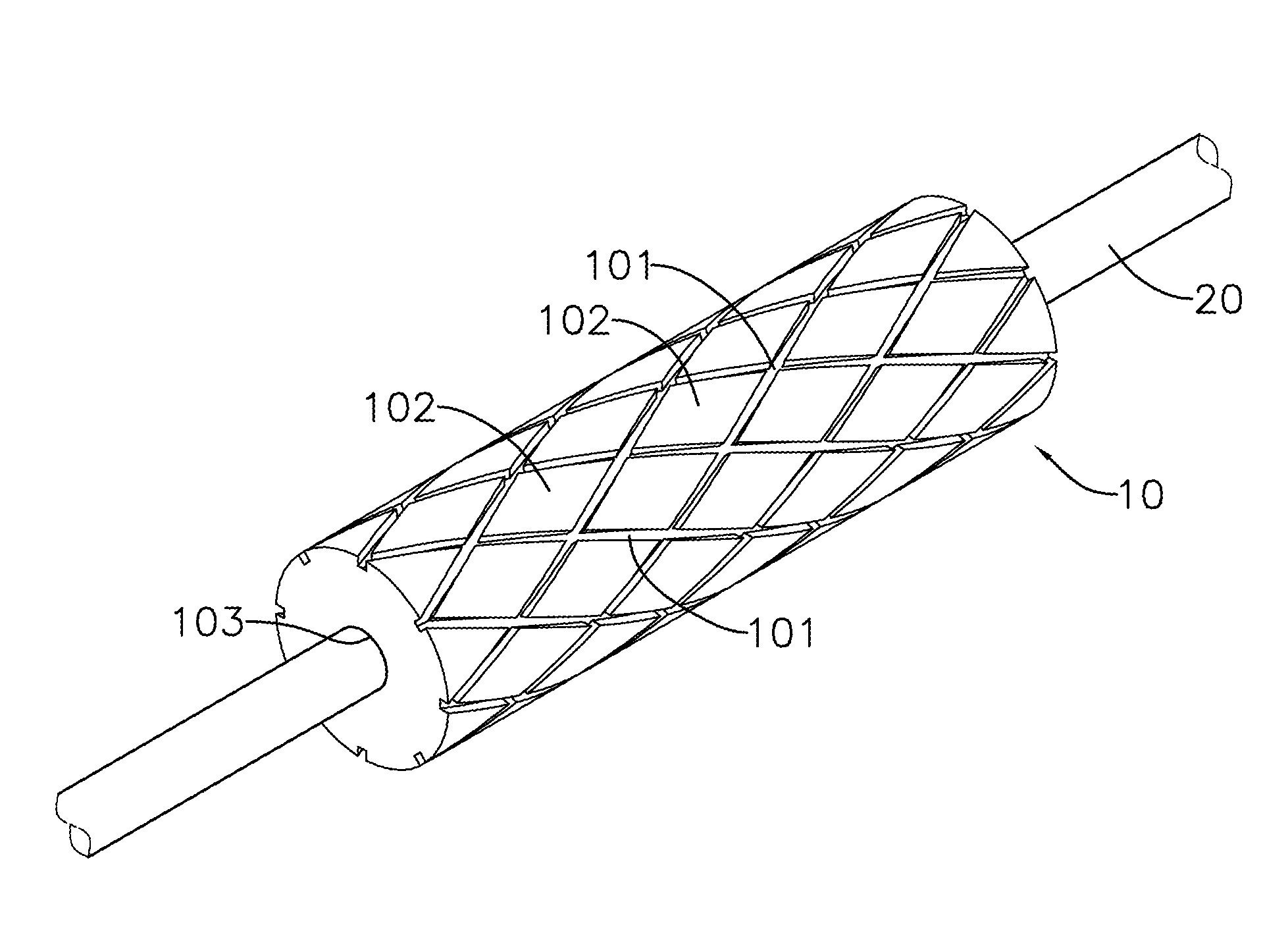
[0012]The present invention, please refer to FIG. 3 to FIG. 5, relates to a roller structure of a business machine which is essentially consisting of:

[0013]A roller 10, wherein a plurality of intersecting grooves 101 are provided on its friction surface to form a number of contact areas 102 simultaneously at the outer surface in the lateral direction along the roller 10 during the whole rotating process. The roller 10 structure can be made of an elastic rubber material.

[0014]A shaft 20, which drives the roller 10, is correspondingly installed through the insertion passage 103 located at the center of roller's cylindrical structure.

[0015]With the intersecting distribution of grooves 101, diamond-shaped contact areas 102 are created without any friction gaps to provide a better and more convenient function of a business machine. Above all, the present invention can provide a longer life expectancy of the roller parts.

[0016]Besides a net-like distribution of those near diamond-shaped c...


PUM

PropertyMeasurementUnit
Forceaaaaaaaaaa
Structureaaaaaaaaaa
Lengthaaaaaaaaaa

Abstract

This present invention relates to a roller structure of a business machine, including a roller and a shaft, by which a plurality of intersecting grooves are provided on the friction surface of the roller so as to form a plurality of contact areas simultaneously on the outer surface in the lateral direction along the roller during the whole rotating process, and the shaft, driving the roller, is correspondingly installed through the insertion passage located at the center of its cylindrical structure of the roller, so as to enable feeding and aligning the paper more silently and stably with a better friction force, to accommodate the dirt or paper dust generated, and thus enhancing the life expectancy of the roller parts.

Description

CROSS-REFERENCE TO RELATED APPLICATIONS[0001]This non-provisional application claims priority under 35 U.S.C. §119(a) on Patent Application No(s). 098214795 filed in Taiwan, R.O.C. on Aug. 11, 2009, the entire contents of which are hereby incorporated by reference.BACKGROUND OF THE INVENTIONPrior Art[0002]Accordingly, a prior application of a roller structure of a business machine (shown in FIG. 1) primarily consists of a roller 30 and a shaft 40, which the roller 30 is configured by a direct and complete touching with the paper to be printed. Initially, it might provide a practical frictional function for paper feeding. However, after a period of use, there will be more and more feeding errors or paper jams occurring during the process of operation due to lowered friction which results from the accumulation of dust or tiny paper pieces. There is another prior roller structure of a business machine (shown in FIG. 2) mainly consisting of a roller 50 and a shaft 60, wherein the roller...

Claims


Application Information

Patent Timeline
IPC IPC(8): A01B29/00
CPCB65H27/00G03G15/0818G03G5/10B65H2404/52131
Inventor CHOU, CHIH HUANG
Owner CHOU CHIH HUANG
Why Eureka
Try Eureka