Motorcycle

a technology for motor vehicles and motorcycles, applied in the field of motor vehicles, can solve the problems of difficult backward movement by manpower, almost impossible to go up the slope, and difficult to move a large motorcycle, etc., and achieve the effects of improving safety, running speed, and easy control

Inactive Publication Date: 2011-02-17
KOKUSAN DENKI CO LTD
View PDF8 Cites 18 Cited by
  • Summary
  • Abstract
  • Description
  • Claims
  • Application Information

AI Technical Summary

Benefits of technology

According to the present invention, since the power source other than the engine is used for the assisted running, the assisted running can be performed by a manipulation different from the manipulation to perform the normal operation. Therefore, the driver can consciously perform the assisted operation, and the vehicle can be prevented from suddenly moving backward despite the intention of the driver because of an erroneous operation. In general, the dynamo electric machine can be easily controlled to gradually increase the rotational speed to a preset speed, and this holds true for the motor generator. Therefore, by using the motor generator as a power source for the assisted running, the running speed during the assisted running can be easily set in a safe range (2 to 3 km / h, for example), and thus the safety is improved.
In addition, according to the present invention, simply adding the sub-clutch between the crankshaft of the engine and the power transmission device enables power transmission from the motor generator to the driving wheel, and there is no need to provide the conventional power transmission mechanism having a one-way clutch between the motor and the engine and a one-way clutch between the motor and the driving wheel, so that the construction of the power transmission device can be prevented from being complicated. In addition, since the motor generator that doubles as a motor and a generator is used as the dynamo electric machine, the engine can have a simple construction and a small size compared with the conventional motorcycle having an engine incorporating two dynamo electric machines, that is, a motor used for engine start and a generator used for battery changing.
According to the present invention, since the engine stop command is generated when a mode other than the normal operation mode is selected, the engine can be kept stopped when the assisted running is performed using the motor generator as a power source. Therefore, it is possible to prevent the vehicle from suddenly being driven by the engine to start running despite the intention of the driver when the sub-clutch is accidentally turned on because of an erroneous operation during the assisted running, and thus the safety is improved.
According to the construction described above, turn on and off of the sub-clutch occurs only when the engine is stopped, so that it is not necessary to consider a situation where the sub-clutch is used in a half-clutch position. Therefore, the sub-clutch can be a clutch that has a simple structure including no synchronization mechanism, and the cost increase due to the addition of the sub-clutch can be minimized.

Problems solved by technology

However, a large motorcycle is hard to move backward by man power because the vehicle weight is very heavy.
It may be barely possible to move the large motorcycle backward by man power on a flat ground, but it is almost impossible to move it backward on a slope and go up the slope.
However, if an engine is used as a power source for moving a vehicle backward, the vehicle can suddenly start moving backward despite the intention of a driver when the driver opens a throttle by mistake when the backward gear is engaged.
Therefore, the conventional motorcycles that use a motor as a power source for moving the vehicle backward have a problem that the engine is mechanically complicated and bulky.
However, the conventional motorcycles are comprised so that the reverse rotation of the motor is transmitted to the driving wheel via the one-way clutch, and therefore, the forward rotation of the motor cannot be transmitted to the driving wheel to move the vehicle forward.

Method used


Image

  • Motorcycle
  • Motorcycle
  • Motorcycle

Examples


Embodiment Construction

In the following, embodiments of the present invention will be described in detail with reference to the drawings.

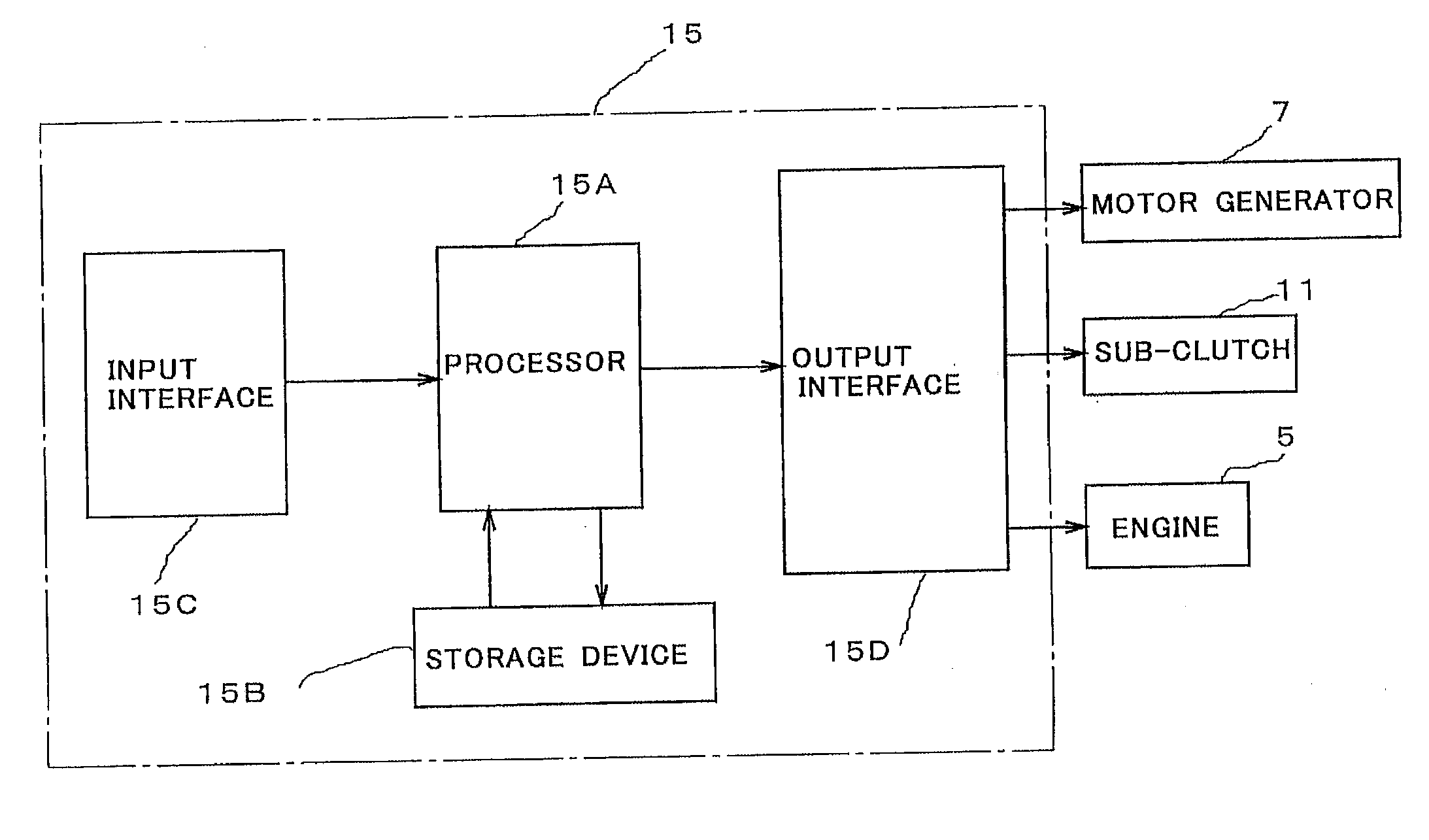
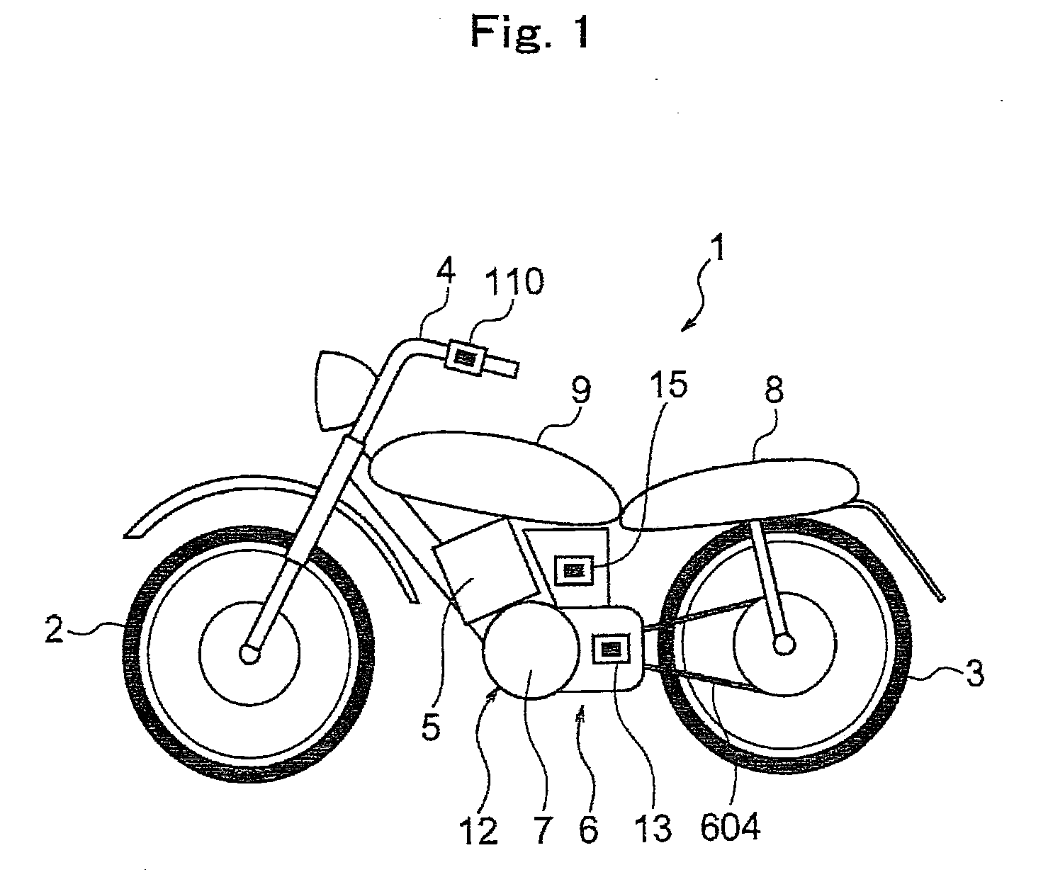
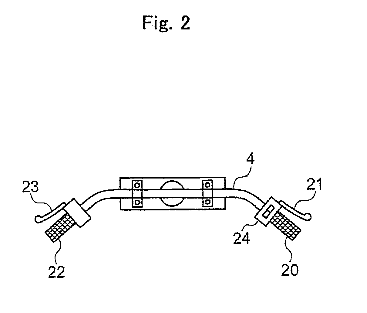
FIG. 1 shows an example of a motorcycle 1 that has an engine as a power source. As shown in this drawing, the motorcycle 1 comprises a steering wheel (front wheel) 2, a driving wheel (rear wheel) 3, a handle 4 attached to the steering wheel 2, an engine 5 that runs under the control of an engine controlling section, a power transmission device 6 that transmits an output power of the engine 5 to the driving wheel 3, and a motor generator (MG) 7 coupled to the engine 5 and the driving wheel 3 via the power transmission device 6. A reference numeral 8 denotes a seat on which a driver sits, and 9 denotes a fuel tank.

As shown in FIG. 3, the power transmission device 6 comprises a transmission 601, an engine-side power transmission mechanism 602 that transmits the output power of the engine 5 to the transmission, a main clutch 603 inserted between the transmission and the engi...


PUM


Abstract

A motorcycle that transmits a rotation of an engine to a driving wheel via a power transmission device having a main clutch comprises a sub-clutch inserted between the power transmission device and an output shaft of the engine and a motor generator having a rotating shaft coupled to the power transmission device and is comprised so that the rotating shaft of the motor generator is coupled to the engine via the sub-clutch and to the driving wheel via the main clutch, and the motorcycle can be moved backward by turning off the sub-clutch and transmitting a rotation of the motor generator to the driving wheel via the main clutch.

Description

TECHNICAL FIELDThe present invention relates to a motorcycle that has an engine as a power source for running.BACKGROUNDA transmission of a motorcycle usually has no backward gear, so that a driver has to push a vehicle backward when the vehicle needs to be moved backward to turn the vehicle in a narrow space or put the vehicle into a garage, for example. A small motorcycle can be moved backward by man power because the vehicle weight is relatively light. However, a large motorcycle is hard to move backward by man power because the vehicle weight is very heavy. It may be barely possible to move the large motorcycle backward by man power on a flat ground, but it is almost impossible to move it backward on a slope and go up the slope.A transmission of a large motorcycle may have a backward gear. However, if an engine is used as a power source for moving a vehicle backward, the vehicle can suddenly start moving backward despite the intention of a driver when the driver opens a throttle...

Claims


Application Information

Patent Timeline
Patent Type & Authority Applications(United States)
IPC IPC(8): B60W10/08B60W20/00B60W10/06B60W10/02B60L50/16
CPCB60K6/48Y02T10/70B60L11/14B60L2200/12B60L2240/421B60L2240/486B60W10/02B60W10/06B60W10/08B60W20/00B60W2510/081B60W2540/10B60W2540/16B60Y2200/12Y02T10/6221Y02T10/6286Y02T10/642Y02T10/7077B60L11/007B60L11/02B60K2006/268B60L50/10B60L50/16B60L50/20Y02T10/62Y02T10/64Y02T10/7072B60W20/40
Inventor KISHIBATA, KAZUYOSHI
Owner KOKUSAN DENKI CO LTD
Why Eureka
Try Eureka