Method of controlling nox purification system, and nox purification system

a technology of nox purification system and nox catalyst device, which is applied in the direction of machines/engines, mechanical equipment, separation processes, etc., can solve the problems of inability to achieve the object of enhancing, inaccurate estimation of the ratio of no to no/sub>2 /sub> with the conventional method, and inability to achieve the effect of enhancing conventional methods. achieve the effect of enhancing the capability of the selective reduction type nox catalyst device, reducing the volume of nox

Active Publication Date: 2011-02-24
ISUZU MOTORS LTD
View PDF3 Cites 32 Cited by
  • Summary
  • Abstract
  • Description
  • Claims
  • Application Information

AI Technical Summary

Benefits of technology

[0026]The method of controlling a NOx purification system and the NOx purification system according to the present invention causes the NOx purification system, in which the oxidation catalyst device for oxidizing NO in the exhaust gas to NO2 is installed in the stage before (at the upstream side of) the selective reduction type NOx catalyst device, to judge whether or not the adsorption of NO2 in the oxidation catalyst device reaches saturation on the basis of the increase or decrease in the volume of adsorbed NO2, and thus to control the amount of exhaust gas to be allowed to pass the bypass passage on the basis of the estimated volume of adsorbed NO2. This allows controlling the volume of NO in the exhaust gas to be converted to NO2.
[0027]In addition, the method and the system according to the present invention allows estimating the proportion of NO2 (or the ratio of NO to NO2) in NOx which flows into the selectiv

Problems solved by technology

For this reason, an unexpectedly large volume of NOx is supplied to the selective reduction type NOx catalyst.
Thus, the estimation of the ratio of NO to NO2 with the method of the conventional technique which gives no consideration to the adsorption of NO2 is inaccurate.
Consequently, the conventional method cannot achieve the object of e

Method used


Image

  • Method of controlling nox purification system, and nox purification system
  • Method of controlling nox purification system, and nox purification system
  • Method of controlling nox purification system, and nox purification system

Examples


Embodiment Construction

[0091]Referring to the drawings, descriptions will be provided for a method of controlling a NOx purification system and the NOx purification system according to an embodiment of the present invention by citing a NOx purification system for purifying NOx in an exhaust gas which passes an exhaust gas passage of a diesel engine.

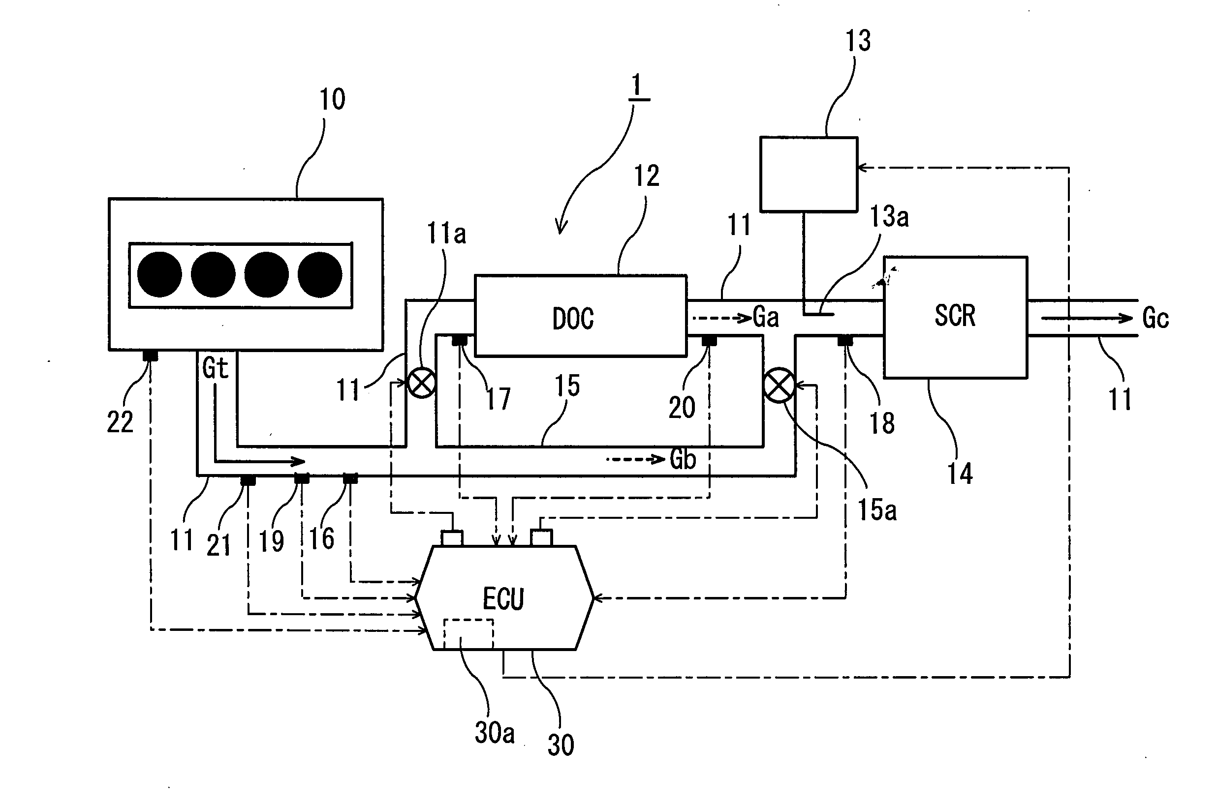
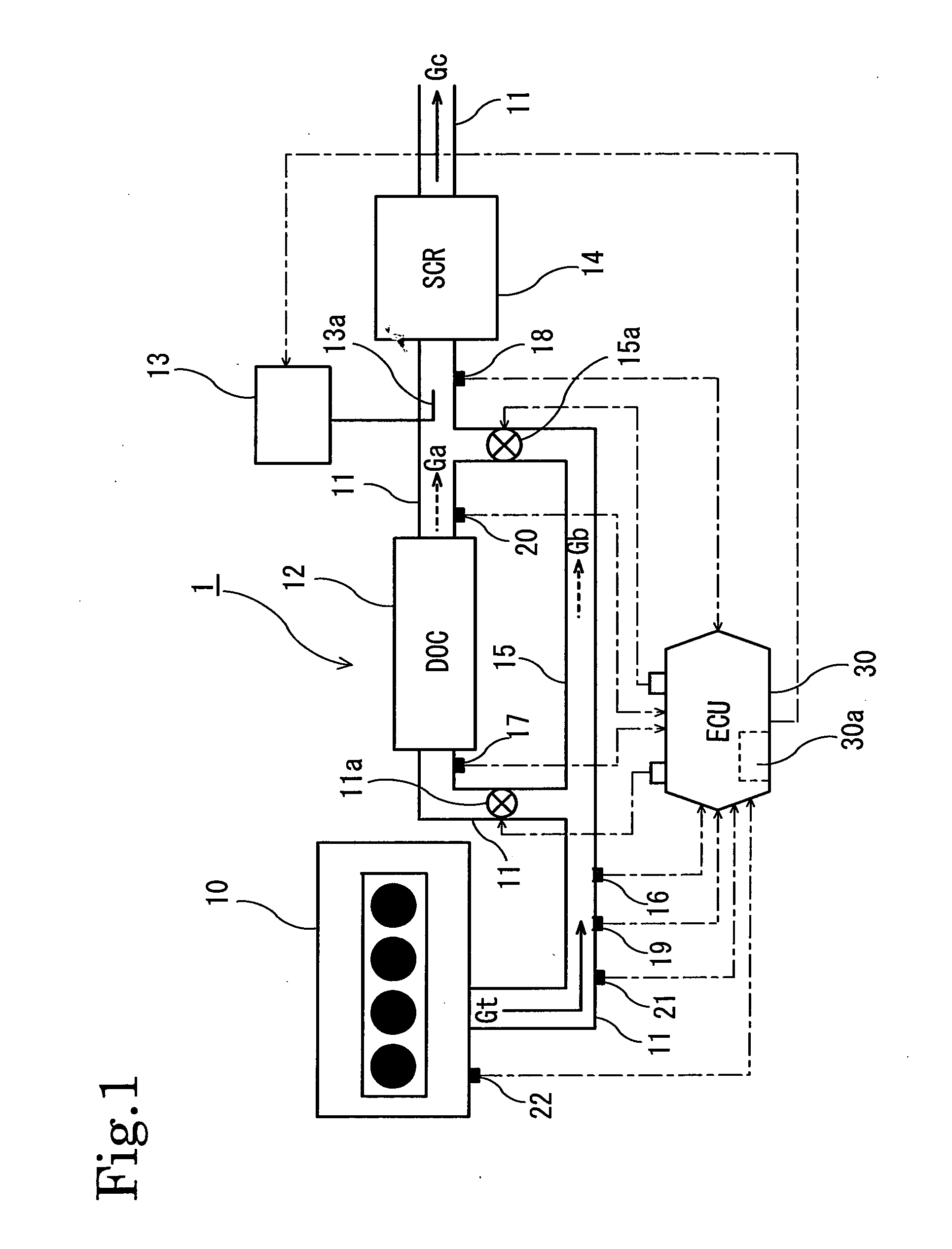
[0092]FIG. 1 shows a configuration of a NOx purification system 1 according to the embodiment of the present invention. In this NOx purification system 1, to an exhaust gas passage 11 of a diesel engine 10, an oxidation catalyst device (DOC) 12, an ammonia-based solution supply unit 13 for supplying an ammonia-based solution to the exhaust gas passage 11, and a selective reduction type NOx catalyst device (SCR) 14 are provided in this order from an upstream side of the exhaust gas passage 11. In addition, a bypass passage 15 which bypasses the oxidation catalyst device 12 is provided in a way to branch from the exhaust gas passage 11 at an upstream side of the ...


PUM

PropertyMeasurementUnit
Fractionaaaaaaaaaa
Temperatureaaaaaaaaaa
Flow rateaaaaaaaaaa

Abstract

Provided is a method of controlling a NOx purification system configured to reduce NOx contained in an exhaust gas by including an oxidation catalyst device (12) and a selective reduction type NOx catalyst device (14), which are arranged in this order from the upstream side, as well as the NOx purification system (1). The method and the system estimates whether a volume (Vn) of NO2 adsorbed in the oxidation catalyst device (12) increases or decreases, and controls a flow rate (Vgb) of exhaust gas which bypasses the oxidation catalyst device (12) on the basis of the increase or decrease in the estimated volume (Vn) of adsorbed NO2. Thereby, the method and the system avoid problems which occur due to shortage and excessive supply of ammonia by: estimating how much of NO2 is adsorbed in the oxidation catalyst device; thus making the ratio of NO to NO2 in NOx, which flows into the selective reduction type NOx catalyst device, closer to 1:1 as much as possible; and adding a necessary amount of ammonia-based solution.

Description

TECHNICAL FIELD[0001]The present invention relates to a method of controlling a NOx purification system which includes an oxidation catalyst device on an upstream side of an exhaust gas passage and a selective reduction type NOx catalyst (SCR catalyst) device on a downstream side of the exhaust gas passage, and to the NOx purification system.BACKGROUND ART[0002]A NOx purification system using a selective reduction type NOx catalyst device has been put in practical use in order to process NOx (nitrogen oxide) in an atmosphere of excessive oxygen in a process for the purification of an exhaust gas from a diesel engine. This NOx purification system provided with the selective reduction type NOx catalyst device includes: a selective reduction type NOx catalyst (SCR catalyst) device for selectively reducing NOx by using ammonia (NH3) as a reducing agent; and as an ammonia supply source, an ammonia-based solution supply unit for adding an ammonia-based solution, such as an aqueous urea so...

Claims


Application Information

Patent Timeline
IPC IPC(8): F01N3/20F01N9/00
CPCB01D53/9431B01D53/9495B01D2251/2062B01D2257/404F01N3/0814F01N3/103F01N13/009F01N3/208F01N2410/00F01N2410/12F01N2610/02Y02T10/24F01N3/2053F01N3/106F01N3/2066F01N2560/026Y02A50/20Y02T10/12
Inventor FUJITA, TETSUYA
Owner ISUZU MOTORS LTD
Why Eureka
Try Eureka