Sealing Grommet

Inactive Publication Date: 2011-02-24
UPSITE TECH INC
View PDF34 Cites 8 Cited by
  • Summary
  • Abstract
  • Description
  • Claims
  • Application Information

AI Technical Summary

Benefits of technology

[0007]The present invention relates to an improved form of sealing grommet of the general type disclosed in the above-mentioned '999 patent, which incorporates a novel form of impermeable, flexible elastomeric sealing member providing highly efficient sealing under all operating conditions. An almost perfect seal is provided when no pass-thro

Problems solved by technology

Because of significant heat generated by servers in a data center, and the detrimental effect of such heat on computer performance, it is customary to provide for cooling the servers, usually by supplying conditioned air to the equipment racks.
It

Method used


Image

  • Sealing Grommet
  • Sealing Grommet
  • Sealing Grommet

Examples


Example

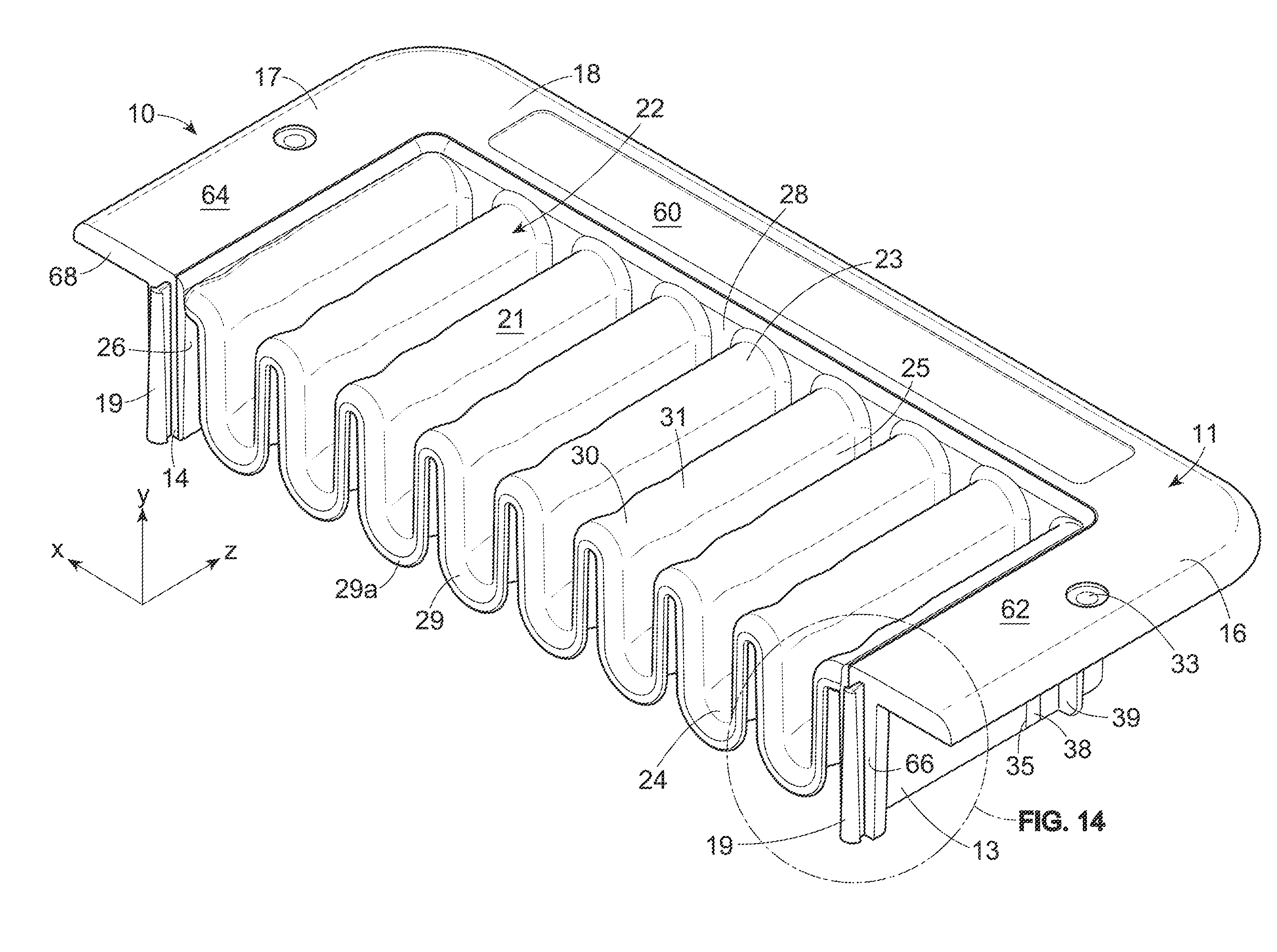
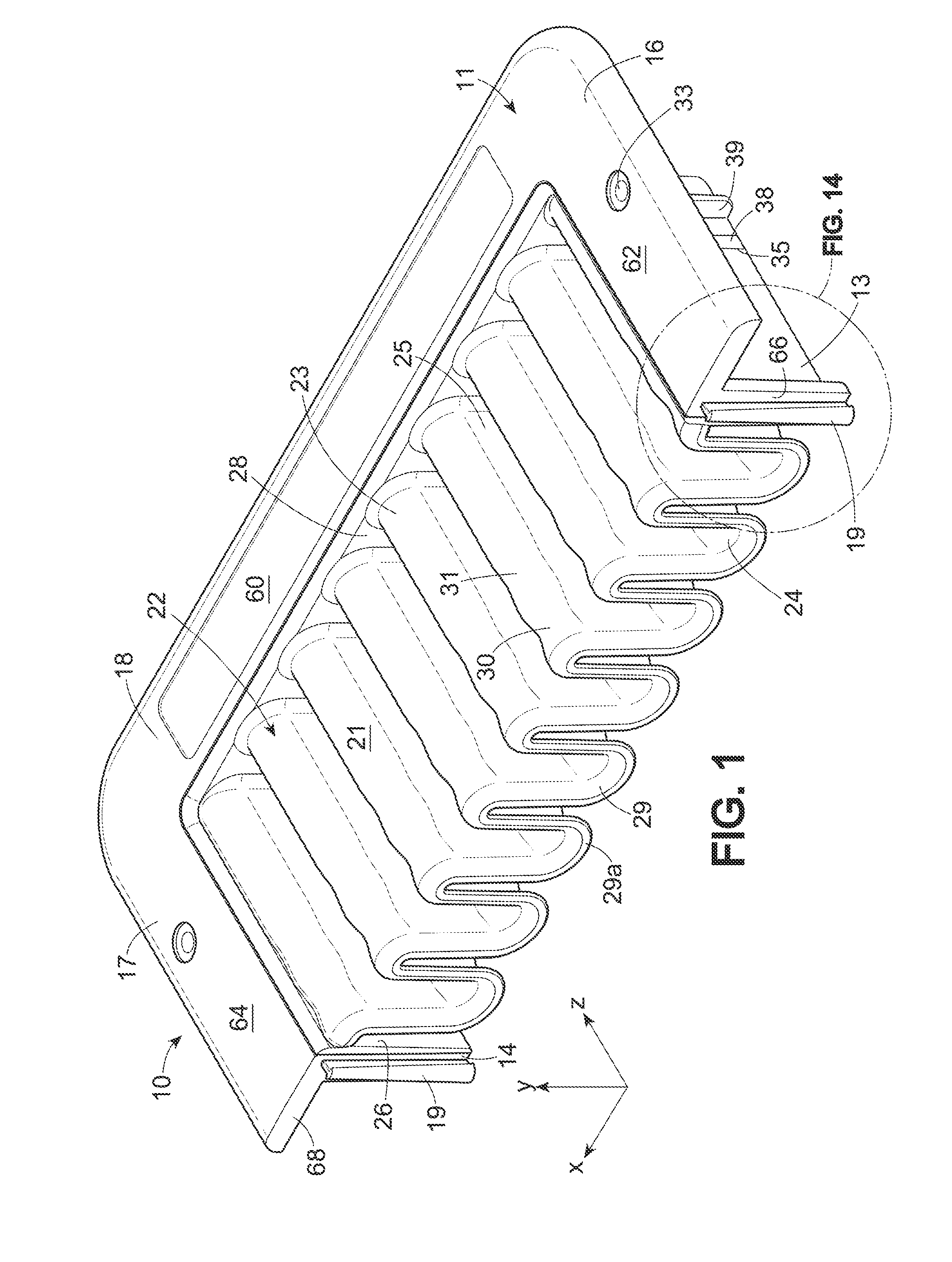
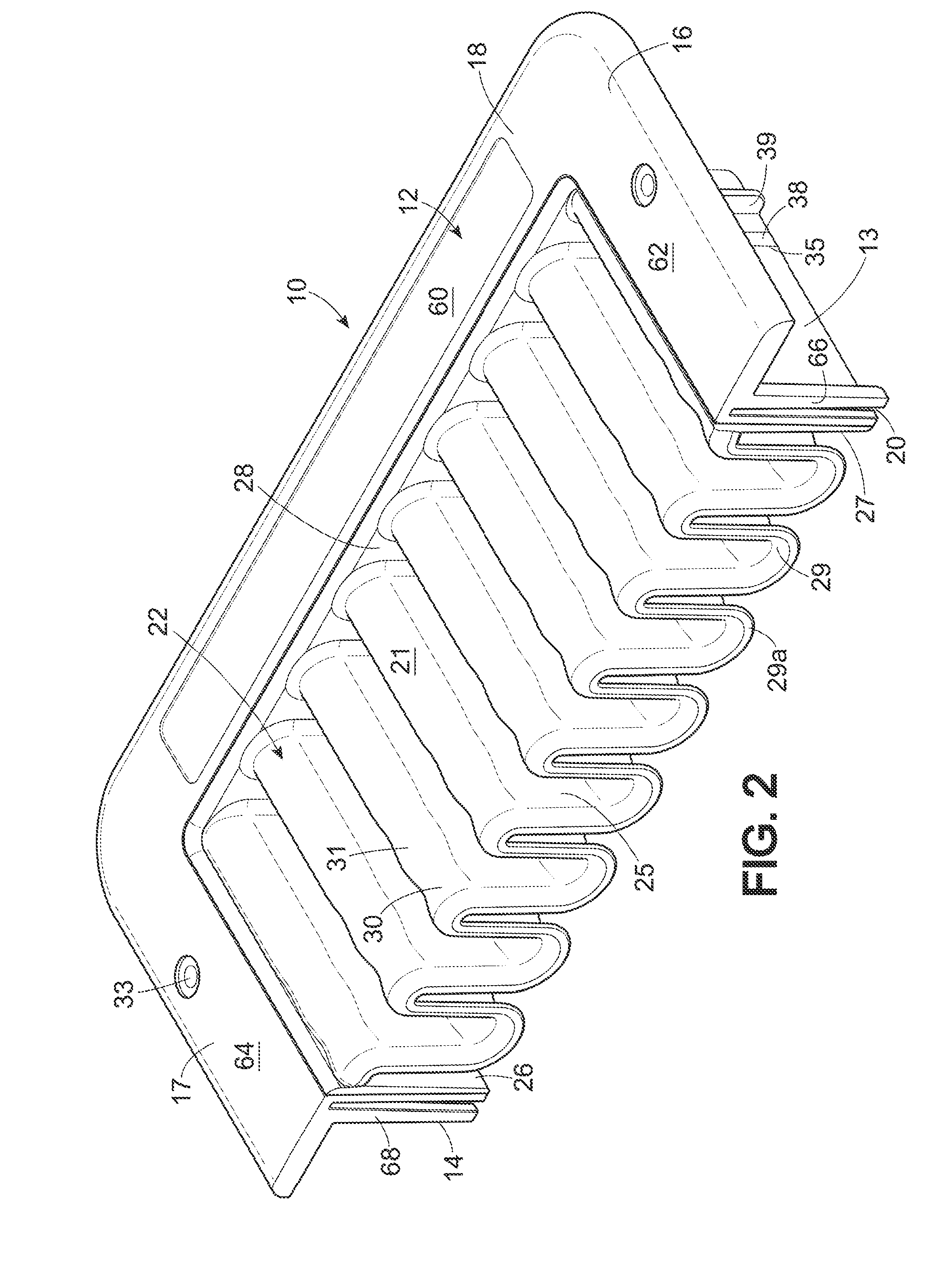
[0042]Referring now to the drawings, and initially to FIGS. 1-4 thereof, the numeral 10 designates generally a sealing grommet according to a preferred embodiment of the invention. The grommet comprises an external frame formed of two half-sections 11, 12 of generally U-shaped configuration. Each frame section 11, 12 has a back portion 60 and two opposed side portions 62, 64 extending from opposite ends of the back portion 60. Each of the back and side portions 60, 62, 64 preferably has an inverted L-shaped cross section defined by a vertical wall 13, 14, 15 (see FIG. 7), dividing the frame into inner and outer portions, and an outwardly extending horizontal flange 16, 17, 18. The illustrated grommet is intended to be seated in or over a generally rectangular service opening (not shown) of about 6 by 8 inches in size, although it will be understood that the grommet of the invention may take a variety of shapes and sizes depending upon requirements.

[0043]FIGS. 1 and 2 illustrate indi...


PUM


Abstract

A sealing grommet, particularly for data centers and the like, formed of one or a pair of U-shaped frame sections, each co-molded with a thermoplastic elastomeric seal of corrugated wave form, with corrugated edges of the seals exposed at the open sides of the U-shaped frames. A pair of such grommet sections joined together, with the corrugated edges arranged to be in contact and in phase, provides a uniquely efficient seal to hold back air under pressure while allowing various pass-through elements, such as cables, hoses, etc., to be extended through the grommet and while enabling the pass-through elements to be easily added, removed, or rearranged as may be necessary to accommodate the dynamic changes experienced in the operation of a data center.

Description

CROSS-REFERENCE TO RELATED APPLICATIONS[0001]This application claims the priority of Provisional Application No. 61 / 235,897, filed Aug. 21, 2009, the entire content of which is incorporated herein by reference.FIELD OF THE INVENTION[0002]The invention relates to grommets and similar devices used for sealing openings in pressurized enclosures such as those provided for supplying conditioned air to electronic equipment in data centers and the like while allowing cables, hoses, conduits and the like to pass through the openings.BACKGROUND OF THE INVENTION[0003]In data centers in particular, and in a variety of other circumstances as well, there is a need and desire to provide for the passage of cables, conduits, hoses and other pass-through elements, through openings in floors, walls, ceilings, cabinet panels, etc., while providing for effective sealing of the opening and at the same time accommodating the efficient addition and / or removal and / or rearrangement of the pass-through eleme...

Claims


Application Information

Patent Timeline
IPC IPC(8): H01B17/26F16L5/02
CPCE04F15/024F16L5/02Y10T16/063H02G3/22Y10T16/05H02G3/185H02G3/18
Inventor SEMPLINER, ARTHUR T.PETTINGILL, JONATHAN
Owner UPSITE TECH INC
Why Eureka
Try Eureka