Blade outer air seal for a gas turbine engine

Inactive Publication Date: 2009-04-16
RAYTHEON TECH CORP
View PDF24 Cites 56 Cited by
  • Summary
  • Abstract
  • Description
  • Claims
  • Application Information

AI Technical Summary

Benefits of technology

[0009]The featherseal according to the present invention includes a first lateral tab and a second lateral tab which defines a tab space therebetween. The tab space engages a post as the featherseal is slidably engaged into a first featherseal slot of each blade outer air seal (BOAS to close a gap therebetween and thereby minimize leakage). The first lateral tab and the second lateral tab lock the featherseal into the BOAS to prevent fore-aft movement thereof. A longitudinal side of the featherseal opposite t

Problems solved by technology

Although effective, the hardcoating operation is relatively expensive and forms a relative rough surface which may increase leakage from the flowpath.
Without the hardcoating operation, the radial tab will wear relat

Method used


Image

  • Blade outer air seal for a gas turbine engine
  • Blade outer air seal for a gas turbine engine
  • Blade outer air seal for a gas turbine engine

Examples


Example

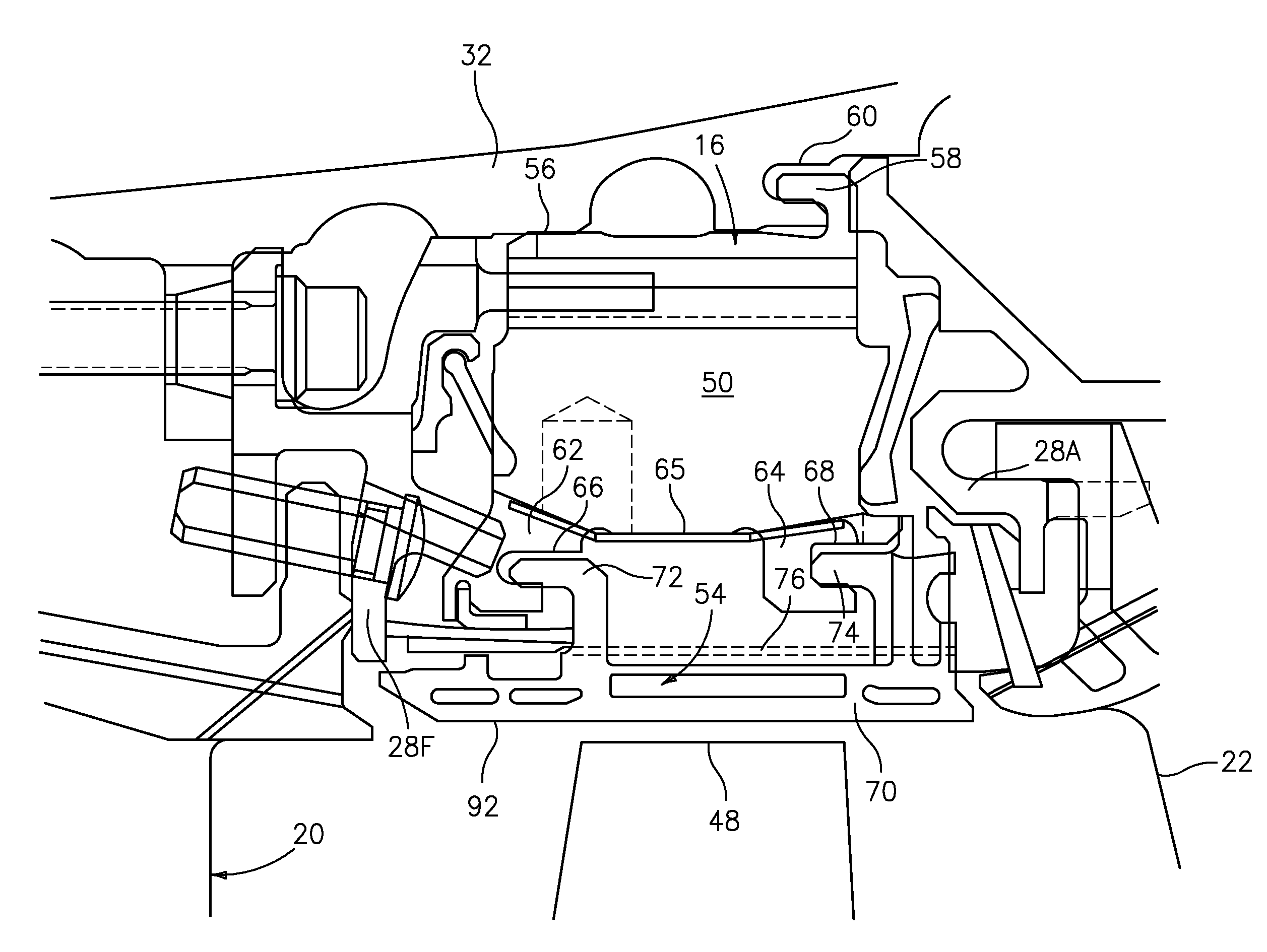
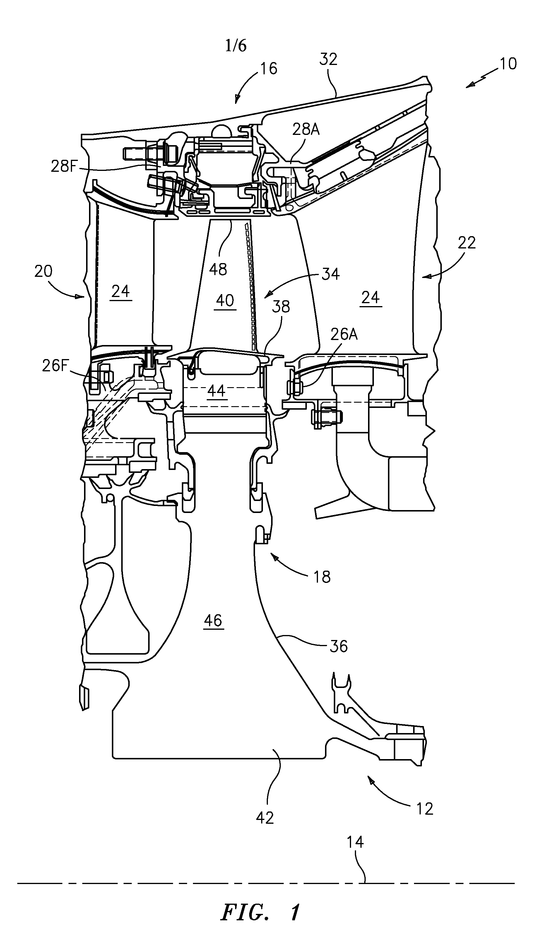
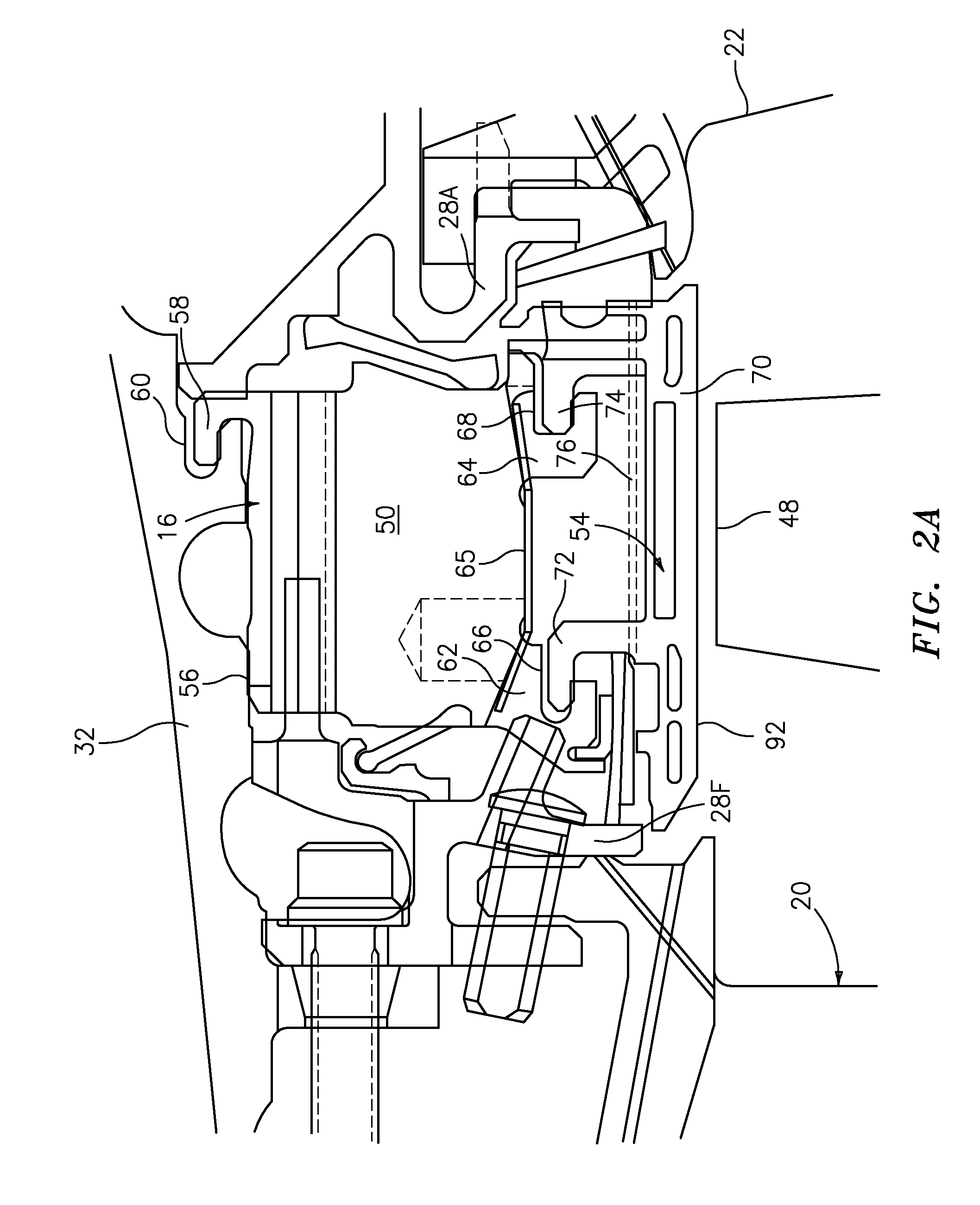
[0020]FIG. 1 schematically illustrates a gas turbine engine 10 (illustrated partially here as a High Pressure Turbine HPT section) having a turbine 12 disposed along a common engine longitudinal axis 14. The illustrated embodiment provides an air seal for high pressure turbine (HPT) blade outer air seal (BOAS) assemblies, also often known as turbine shroud assemblies. It should be understood that although a BOAS for a HPT is disclosed in the illustrated embodiment, the seal arrangement may be utilized in any section of a gas turbine engine. It should also be understood, however, that any type of air seals including seals between vane segments and the like may also benefit here from.

[0021]The air seal produced according to the present invention may find beneficial use in many industries including aerospace and industrial. The air seal may be beneficial in applications including electricity generation, naval propulsion, pumping sets for gas and oil transmission, aircraft propulsion, a...


PUM


Abstract

An air seal assembly includes a featherseal engaged between adjacent turbine engine components to close a gap therebetween. The featherseal includes a first lateral tab and a second lateral tab which defines a tab space therebetween. The tab space locks the featherseal into the turbine engine component to prevent fore-aft movement thereof.

Description

BACKGROUND OF THE INVENTION[0001]This invention was made with government support under Contract No.: N00019-02-C-3003 awarded by the Department of the Navy. The government therefore has certain rights in this invention.[0002]The present invention relates to a gas turbine engine, and more particularly to a featherseal for turbine engine components such as vanes and blade outer air seals (BOAS).[0003]Gas turbine engines generally include fan, compressor, combustor and turbine sections positioned along an axial centerline often referred to as the engine axis of rotation. The fan, compressor, and turbine sections each include a series of stator and rotor blade assemblies. An array of blades and an axially adjacent array of vanes are referred to as a stage.[0004]Each stator assembly, which does not rotate (but may have variable pitch vanes), increase the efficiency of the engine by guiding core gas flow into or out of the rotor assemblies.[0005]Each rotor blade assembly includes a plural...

Claims


Application Information

Patent Timeline
IPC IPC(8): F02C7/28
CPCF01D11/005F05D2240/57F05D2240/11F01D11/08
Inventor SPANGLER, BRANDON W.PAAUWE, CORNEIL S.MONGILLO, DOMINIC J.
Owner RAYTHEON TECH CORP
Why Eureka
Try Eureka