Roll-to-roll processing and tools for thin film solar cell manufacturing

Inactive Publication Date: 2010-09-09
SOLOPOWER
View PDF39 Cites 49 Cited by
  • Summary
  • Abstract
  • Description
  • Claims
  • Application Information

AI Technical Summary

Benefits of technology

[0016]Several embodiments are given for the roll-to-roll tools that improve their versatility and the quality of the semiconductor absorber layers processed using such reactors.
[0017]An aspect of the present invention includes a reactor having multiple exhaust outlets connected to a process gap of the reactor between an entrance opening and an exit opening of the process gap. The entrance opening and the exit opening of the process gap are open to the atmosphere. By controlling each exhaust outlet independently with valves, process times of a precursor layer in different sections of the process gap may be extended or shortened. This versatility of the reactor allows conversion of precursor layers into absorber layers having different compositions and molar ratios using the reactor of the present invention.
[0018]Another aspect of the present invention includes a reactor including multiple gas inlets and exhaust outlets connected to a process g

Problems solved by technology

However, the cost of electricity generated using silicon-based solar cells is higher than the cost of electricity generated by the more traditional methods.
Fo

Method used


Image

  • Roll-to-roll processing and tools for thin film solar cell manufacturing
  • Roll-to-roll processing and tools for thin film solar cell manufacturing
  • Roll-to-roll processing and tools for thin film solar cell manufacturing

Examples


Example

EXAMPLE 1

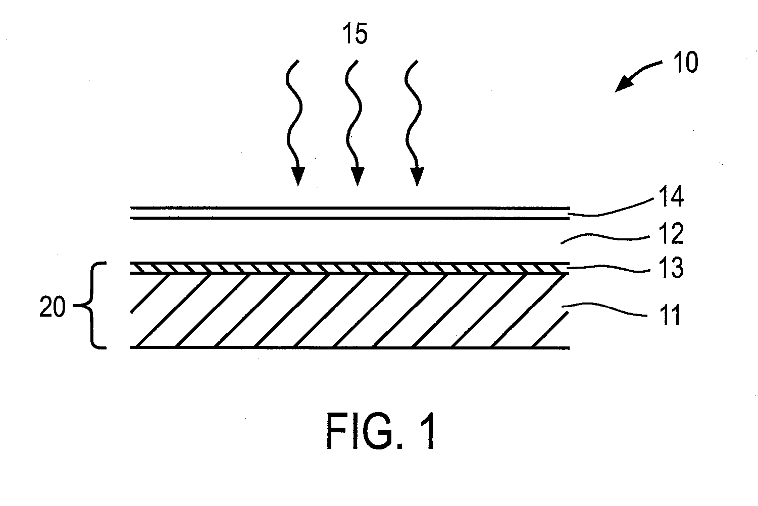
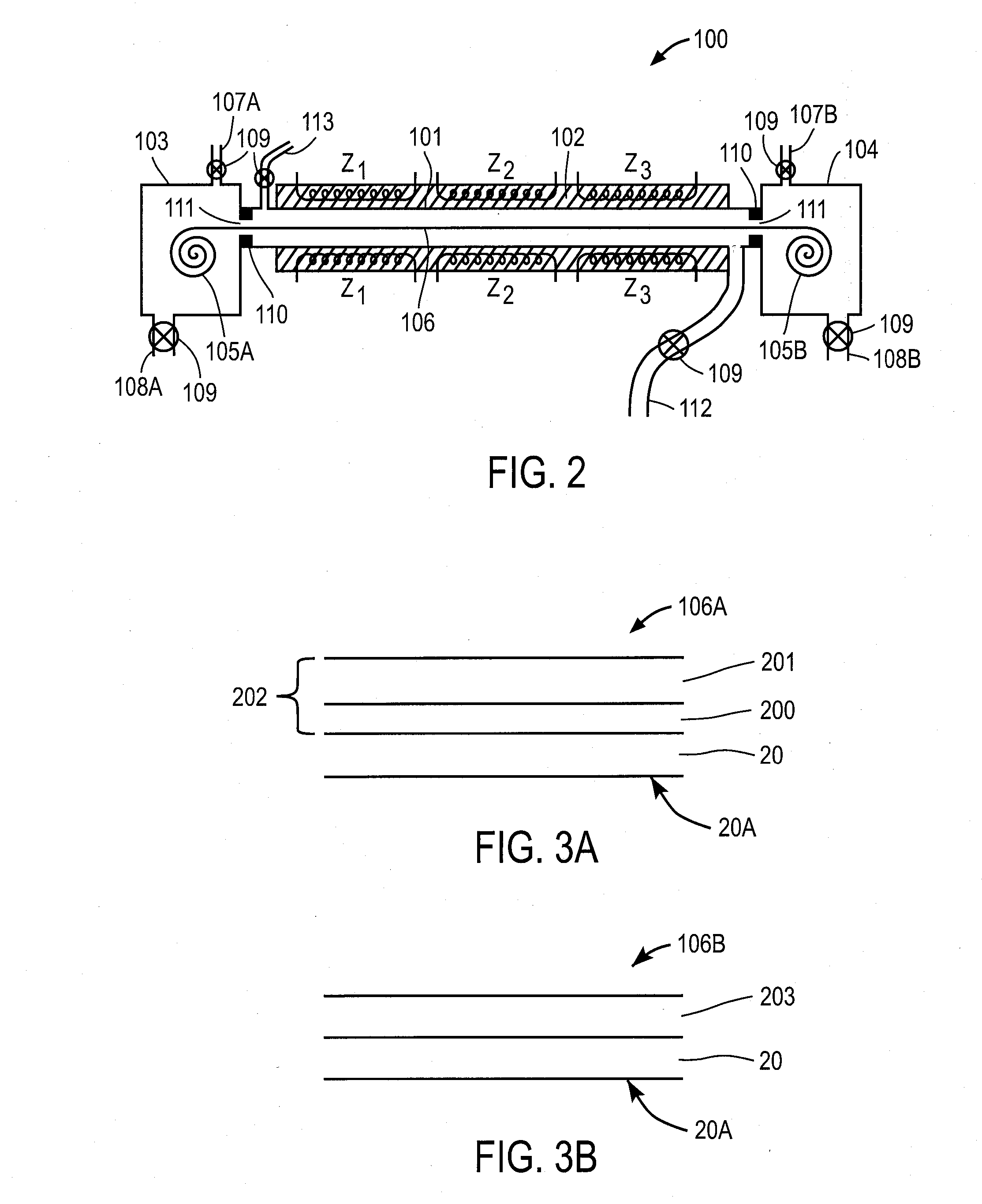
[0076]A Cu(In,Ga)(Se,S)2 absorber layer may be formed using the single chamber reactor design of FIG. 2. An exemplary flexible structure 106A before the reaction is shown in FIG. 3A. The base 20 may be similar to the base 20 of FIG. 1. A precursor layer 200 is provided on the base 20. The precursor layer 200 comprises Cu, and at least one of In and Ga. Preferably the precursor layer 200 comprises all of Cu, In and Ga. A Se layer 201 may optionally be deposited over the precursor layer 200 forming a Se-bearing precursor layer 202. Se may also be mixed in with the precursor layer 200 (not shown) forming another version of a Se-bearing precursor layer. The flexible structure after the reaction step is shown in FIG. 3B. In this case the flexible structure 106B after the reaction comprises the base 20 and the Group IBIIIAVIA compound layer 203 such as a Cu(In,Ga)(Se,S)2 film that is obtained by reacting the precursor layer 200 or the Se-bearing precursor layer 202.

[0077]After lo...

Example

EXAMPLE 2

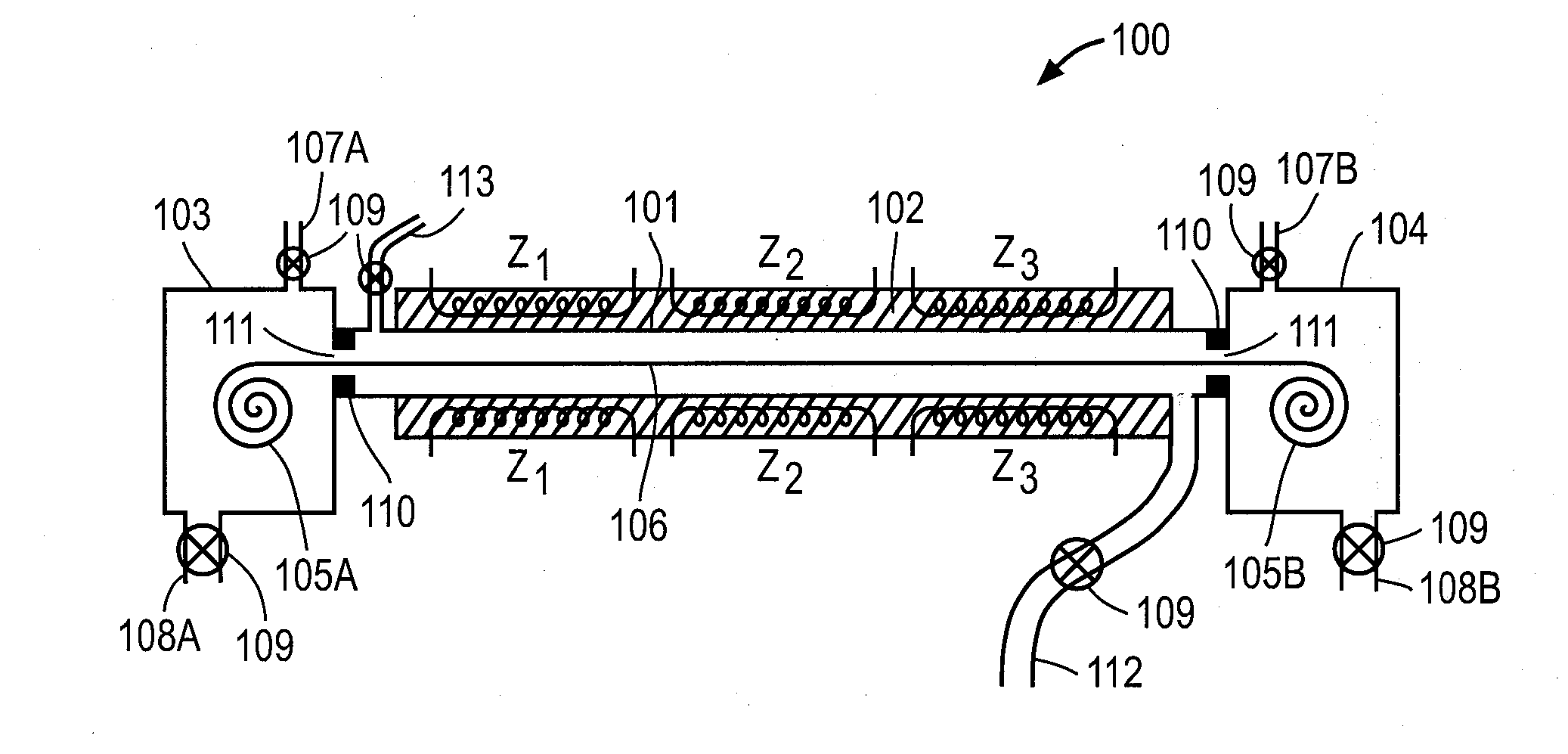
[0085]A Cu(In,Ga)(Se,S)2 absorber layer may be formed using the three-section chamber reactor of FIG. 4. After loading the unreacted flexible structure 106, pumping and purging the system as described in Example 1, the process may be initiated. Sections A, B and C of the three-section chamber 450 may have temperatures of T1, T2 and T3 which may or not be equal to each other. Furthermore, each of the sections A, B and C may have a temperature profile rather than just a constant temperature along their respective lengths. During processing, a first process gas such as N2 may be introduced into the low-volume segment 410 in section B through inlet 403, while a second process gas and a third process gas may be introduced in sections A and C, respectively, through inlets 401 and 402, respectively.

[0086]The second process gas and the third process gas may be the same gas or two different gases. For example, the second process gas may comprise Se and the third process gas may comp...


PUM

PropertyMeasurementUnit
Temperatureaaaaaaaaaa

Abstract

Described are roll-to-roll or reel-to-reel thermal or rapid thermal processing tools (reactors) are used to react a precursor layer on a continuous flexible workpiece. Variants of the reactors are described, including a reactor having multiple exhaust outlets connected to a process gap of the reactor between an entrance opening and an exit opening of the process gap; a reactor including multiple gas inlets and exhaust outlets connected to a process gap of the reactor between an entrance opening and an exit opening of the process gap; a reactor including multiple gas inlets and exhaust outlets connected to a process gap of the reactor between an entrance opening and an exit opening of the process gap; and a reactor including multiple gas inlets and exhaust outlets connected to a process gap of the reactor between an entrance opening and an exit opening of the process gap. Also described is an exhaust system that separates the Group VIA material vapors from other gaseous species for re-cycling or easy disposal and techniques and apparatus for efficient removal of moisture from the workpiece before processing precursor layer in the RTP tool.

Description

CROSS REFERENCE TO RELATED APPLICATIONS[0001]This application claims priority to U.S. Provisional Application No. 61 / 159053 filed Mar. 10, 2009 entitled “EXHAUST SYSTEM FOR ROLL TO ROLL REACTORS EXHAUST SYSTEM FOR ROLL TO ROLL REACTORS”, and this application claims priority to U.S. Provisional Application No. 61 / 161377 filed Mar. 18, 2009 entitled “MOISTURE CAPTURE IN UNWIND AND REWIND STATIONS OF ROLL TO ROLL REACTORS”, and this claims priority to U.S. Provisional Application No. 61 / 162235 filed Mar. 20, 2009 entitled “ROLL-TO-ROLL PROCESSING AND TOOLS FOR THIN FILM SOLAR CELL MANUFACTURING”; and this application claims priority to and is a Continuation-in-Part of U.S. patent application Ser. No. 12 / 344420 filed Dec. 12, 2008, entitled “REACTOR TO FORM SOLAR CELL ABSORBERS” and this application claims priority to and is a Continuation-in-Part of U.S. patent application Ser. No. 12 / 177007 filed Jul. 21, 2008 entitled “METHOD AND APPARATUS TO FORM THIN LAYERS OF PHOTOVOLTAIC ABSORBER...

Claims


Application Information

Patent Timeline
IPC IPC(8): F26B3/28F24F7/00F26B3/34
CPCC23C14/5866F27B9/045F27B9/063F27B9/20F27B9/28Y02E10/541H01L21/67109H01L21/67126H01L21/6776H01L31/0322F27B9/36
Inventor BASOL, BULENT M.ZOLLA, HOWARDPINARBASI, MUSTAFANORSWORTHY, GREGORY
Owner SOLOPOWER
Why Eureka
Try Eureka