Ballast For Fluorescent Emergency Lighting

a ballast and fluorescent technology, applied in emergency power supply arrangements, parallel/serial switching, transportation and packaging, etc., can solve the problems of not being able or convenient to determine the voltage of the light source, the feature is not cost-effective for emergency ballasts, and the system must be resolved

Inactive Publication Date: 2011-02-24
COOPER TECH CO
View PDF15 Cites 58 Cited by
  • Summary
  • Abstract
  • Description
  • Claims
  • Application Information

AI Technical Summary

Benefits of technology

[0017]The charging circuit can also include a thermal protection circuit that prevents application of the charge to the battery when the battery exceeds a predetermined temperature. The thermal protection circuit can include a thermistor thermally coupled to the battery and a resistor electrically coupled to the thermistor such that the resistor and the thermistor create a voltage divider. When the voltage across the resistor exceeds a predetermined level, current can be delivered to a transistor that is electrically coupled to the battery such that when the transistor is not conductive, the charging circuit does not deliver charge to the battery. When current is delivered to the transistor, the transistor becomes conductive and decouples the battery from the charging circuit.

Problems solved by technology

Although simple in concept, there are many issues that emergency lighting systems must resolve.
One such issue relates to the fact that most buildings that have emergency lighting use linear fluorescent lamps to provide illumination.
During a typical installation process, it may not be possible or convenient to ascertain which voltage is carried on any given wire.
Because of the expense associated with this solution, however, the feature is not cost effective for emergency ballasts, and therefore is not used.
Because this information may not be available, the result of this drawback of conventional emergency ballasts can be additional time in installation or troubleshooting, or even a failure of an emergency ballast that has inadvertently been incorrectly installed.
Conventional emergency ballasts also have a problem when switching between standard operational mode, which is controlled through the standard fluorescent ballast, and emergency mode, which is controlled by the emergency ballast.
If this transition occurs quickly, the fluorescent ballast may not have had time to power up properly, causing the fluorescent ballast to identify an open cathode condition and shut down.
Then, because neither the emergency ballast nor the fluorescent ballast are operating, the light fixture will be off, potentially necessitating a call to maintenance to remedy the problem.
Conventional emergency ballasts also suffer from an inability to use certain types of rechargeable batteries.
Conventional emergency ballasts must be made as inexpensively as possible, or risk being unmarketable.
The need to remain inexpensive limits the types of rechargeable batteries that are available for use in emergency ballasts.

Method used


Image

  • Ballast For Fluorescent Emergency Lighting
  • Ballast For Fluorescent Emergency Lighting
  • Ballast For Fluorescent Emergency Lighting

Examples


Embodiment Construction

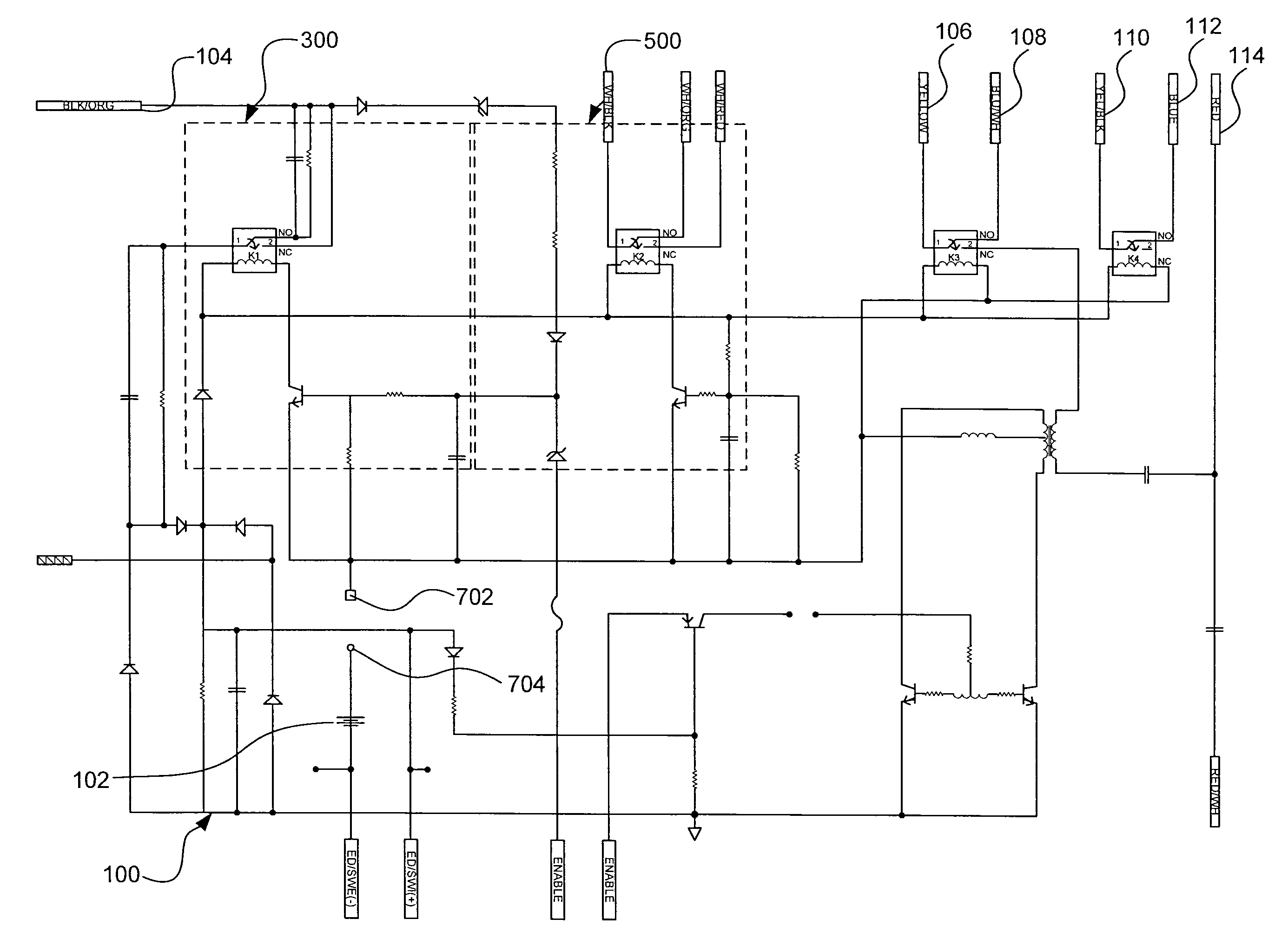
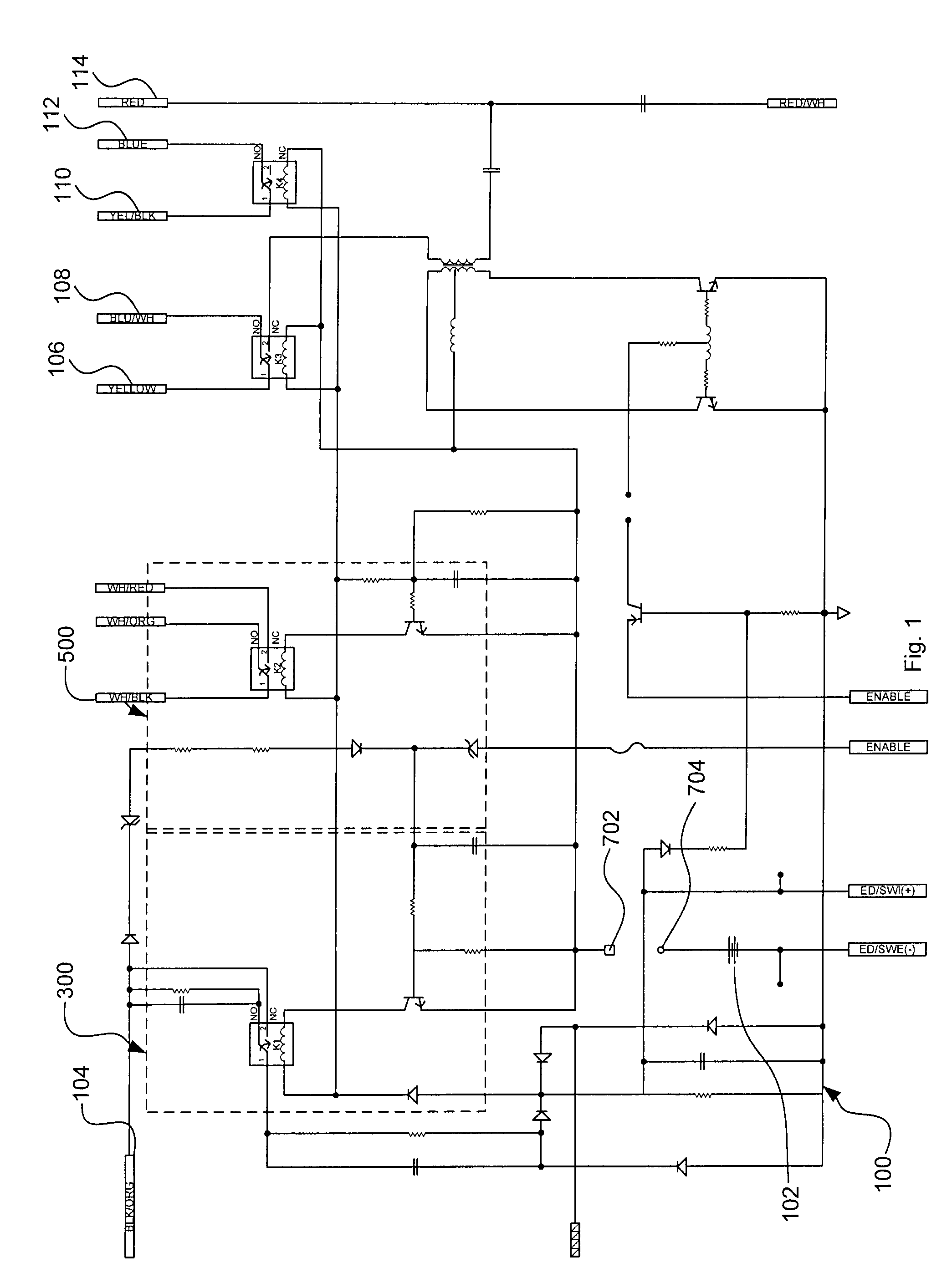
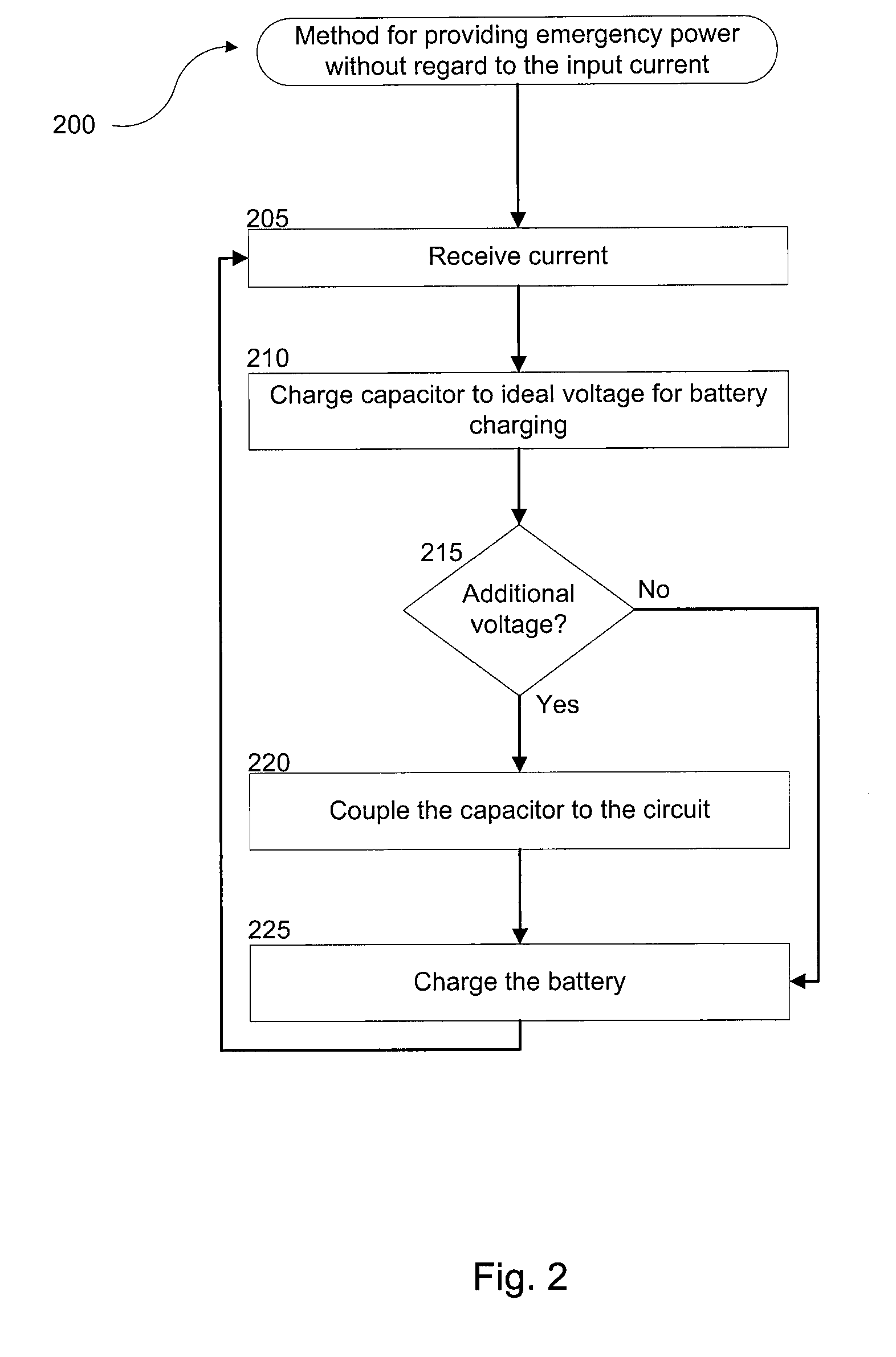
[0031]The present invention is directed to electrical lighting devices. In particular, certain exemplary embodiments of the invention are directed to an emergency fluorescent ballast that is installed in a fixture without regard to the amplitude of the current that is provided to the ballast. Certain other exemplary embodiments of the invention are directed to an emergency fluorescent ballast that uses more advanced battery technology, such as nickel metal hydride, as an emergency power supply. Yet other exemplary embodiments of the invention are directed to an emergency fluorescent ballast that prevents a standard ballast from improperly detecting an end-of-life open cathode condition in the lamp during the switchover from emergency operation to standard operation due to relay bounce.

[0032]The invention may be better understood by reading the following description of non-limiting, exemplary embodiments with reference to the attached drawings, wherein like or corresponding, but not ...


PUM


Abstract

An emergency ballast for a fluorescent lamp includes a rechargeable battery. The emergency ballast also includes a circuit for receiving an electrical current and providing a recommended charging voltage to the battery. The electrical current is one of two amplitudes, and the circuit provides a charge to the battery without regard to the amplitude of the electrical current. The first amplitude of the electrical current can be 120 volts, and the second amplitude can be 277 volts. The emergency ballast includes a capacitor electrically coupled to the circuit that provides an additional voltage to the rechargeable battery when the electrical current is 120 volts. The emergency ballast also includes a switch for electrically decoupling the capacitor from the circuit when the electrical current is 277 volts.

Description

CROSS REFERENCE TO RELATED APPLICATIONS[0001]This non-provisional patent application claims priority to U.S. Provisional Patent Application No. 61 / 234,987, filed on Aug. 18, 2009, the entire contents of which are hereby fully incorporated herein by reference. This application is also related to U.S. patent application Ser. No. ______ , titled “Sinusoidal Alternating Current Ballast For Fluorescent Emergency Lighting,” filed on Aug. 18, 2010, the entire contents of which are hereby fully incorporated herein by reference.TECHNICAL FIELD[0002]The disclosure relates generally to apparatus and methods for providing emergency power to linear fluorescent lamps. More specifically, the disclosure relates to apparatus and methods for providing current to fluorescent lamps using an emergency battery such that the life of the lamp is not shortened unnecessarily.BACKGROUND[0003]Most modern buildings have the capability to provide emergency lighting in the event of an interruption to the main pow...

Claims


Application Information

Patent Timeline
Patent Type & Authority Applications(United States)
IPC IPC(8): H02J9/00H02J7/00H02J7/04
CPCH02J7/0024H05B41/2985H02J9/02H02J7/345
Inventor PORTER, KEVINMANGIARACINA, ANTHONY
Owner COOPER TECH CO
Why Eureka
Try Eureka