
Transceiving circuit for contactless communication and NFC device or RFID reader/writer device comprising such a transceiving circuit

a transceiving circuit and contactless communication technology, applied in the direction of antenna details, instruments, antennas, etc., can solve the problems of drifting out of specifications, current consumption of the transceiving circuit exceeding the specified maximum current consumption imax, and therefore not being acceptable for practical implementation

Active Publication Date: 2011-02-24
QUOTAINNE ENTERPRISES
View PDF17 Cites 23 Cited by
  • Summary
  • Abstract
  • Description
  • Claims
  • Application Information

AI Technical Summary

Benefits of technology

[0008]It is an object of the invention to provide a transceiving circuit for contactless communication of the type defined in the opening paragraph and an NFC device in which the disadvantages defined above are avoided.
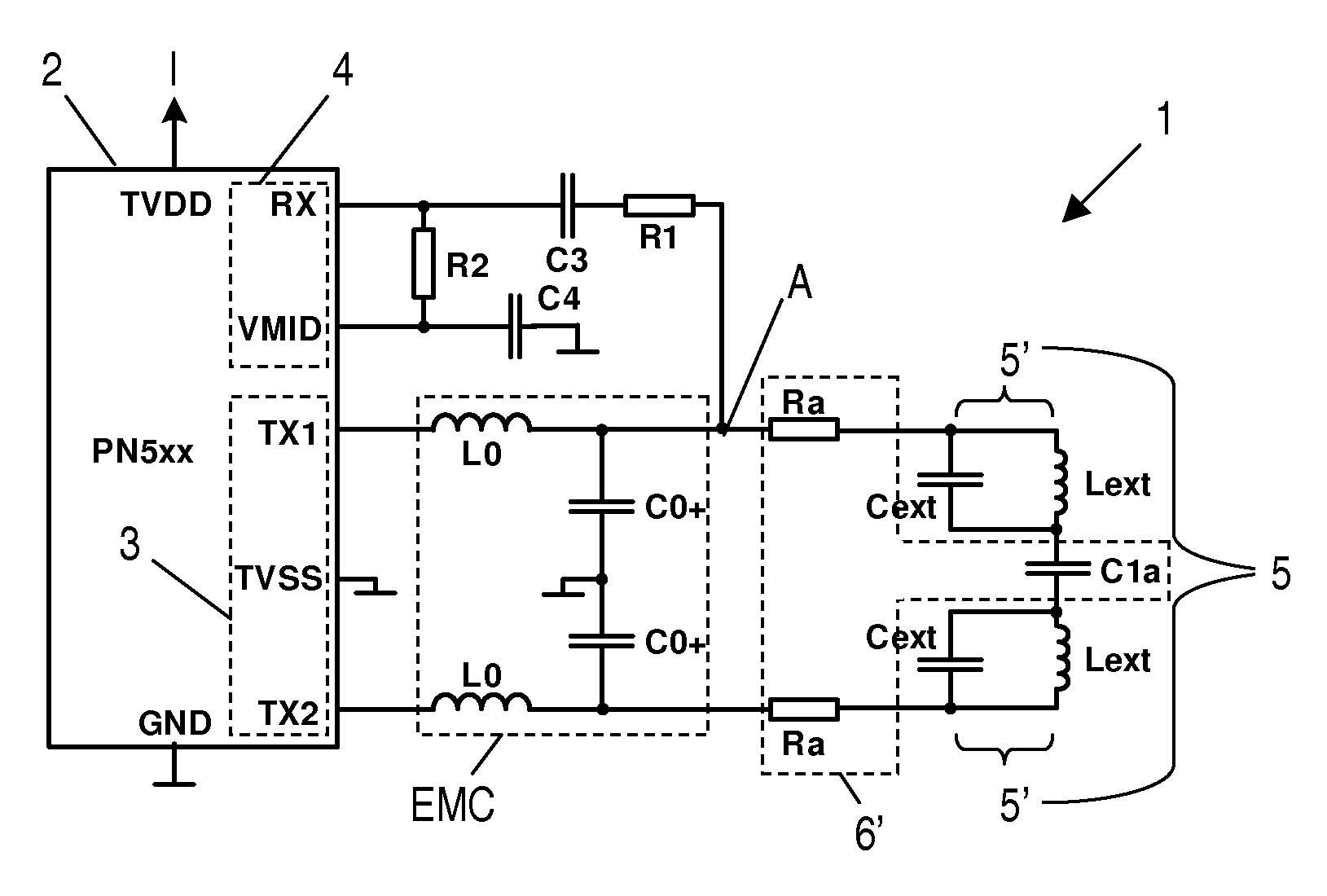
[0014]The characteristic features according to the invention provide the advantage that the circuit can be operated throughout the entire range of distance between the antenna of the circuit and an antenna of a resonant circuit like an NFC card or tag without consuming more current than allowed by the specifications. Specifically, such a transceiving circuit is able to fulfil all specifications of the standard ISO 14443. Particularly the transceiving circuit according to the present invention remains below the maximal allowable current consumption even when the reading distance to the antenna of the resonant circuit becomes zero, and although at distances close to zero the resonant circuit implies a strong detuning effect on the antenna of the transceiving circuit.
[0015]Highly stable and constant values of the absolute values of the matching-impedance MZ of the transceiving circuit is achieved irrespective of a varying distance of the antenna to a resonant circuit like an NFC card when the at least one impedance-matching capacitor is arranged in a transmission path between the antenna and a tapping of a receiving path from the transmission path and / or when the at least one impedance-matching capacitor is arranged in a transmission path between the antenna and an electromagnetic compatibility filter which is connected to output terminals of the transmitter means.
[0016]In an embodiment of the invention the antenna comprises split antenna parts and the impedance-matching capacitor is arranged between antenna parts. This embodiment provides the advantage that since the impedance-matching capacitor is located externally of the integrated transceiving circuit components it is not subject to space limitations. Particularly, the impedance-matching capacitor is arranged at the external antenna side of the circuit which offers plenty of space for arranging electronic components.
[0017]In an alternative embodiment of the invention the transceiving circuit comprises two impedance-matching capacitors, which are serially arranged in transmission paths at both sides of the antenna. This embodiment enables easy trimming of an impedance-matching network of the transceiving circuit during the manufacturing process.

Problems solved by technology

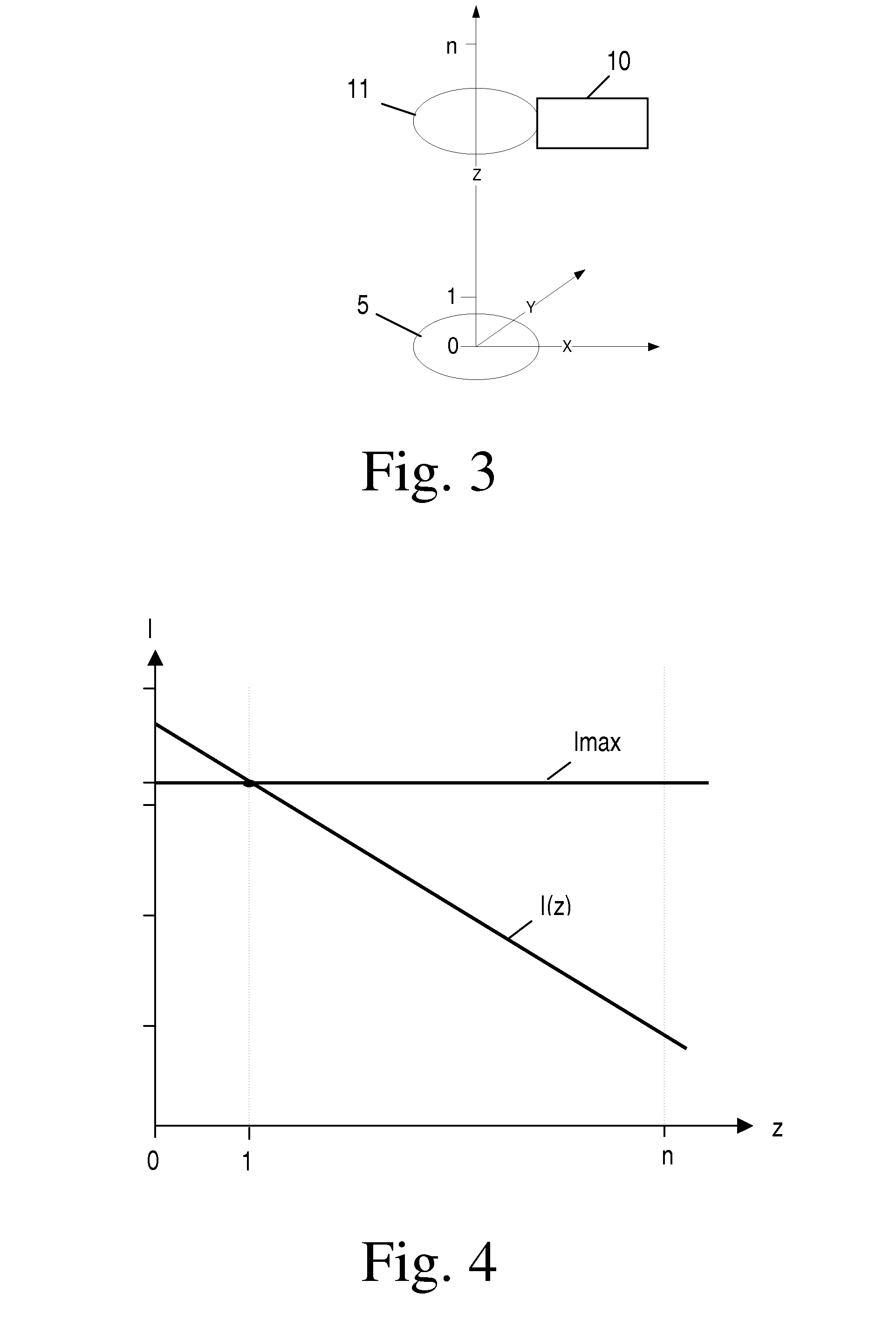
A severe disadvantage of this known transceiving circuit is that due to the chosen manner of antenna tuning the current consumption of the near field communication (NFC) transmission module can vary in such a large range that it even drifts out of the specifications.
It will be appreciated that for distances between the antenna 5 and the antenna 11 smaller than the value 1 the current consumption of the transceiving circuit exceeds the specified maximal current consumption Imax and is therefore not acceptable for practical implementations.

Method used


Image

  • Transceiving circuit for contactless communication and NFC device or RFID reader/writer device comprising such a transceiving circuit
  • Transceiving circuit for contactless communication and NFC device or RFID reader/writer device comprising such a transceiving circuit
  • Transceiving circuit for contactless communication and NFC device or RFID reader/writer device comprising such a transceiving circuit

Examples


Embodiment Construction

[0029]FIG. 5 shows a circuit diagram of a transceiving circuit 1 according to a first embodiment of the present invention. This transceiving circuit 1 comprises an integrated RFID transmission module 2, e.g. a near field communication transmission module of the type no. PN5xx manufactured by NXP Semiconductors, or of the Micore family (MF RC5xx, MF RC632, SL RC400) also manufactured by NXP Semiconductors. The transmission module 2 has a supply terminal TVDD for supplying it with electric current I. The transmission module 2 comprises transmitter means 3 and receiver means 4. The transmitter means 3 of the RFID transmission module 2 generate an electromagnetic carrier signal. The carrier signal is modulated according to transmitting data. An antenna 5 is driven with the modulated carrier signal. The transmission module 2 has output terminals TX1, TX2 being connected to first and second transmitting paths wherein the transmitting paths are connected to the antenna 5, which is represen...


PUM


Abstract

A transceiving circuit (1, 1′) for contactless communication comprises transmitter means (3) being adapted to generate an electromagnetic carrier signal and to modulate the carrier signal according to transmitting data, and an antenna (5) being connected to and driven by the transmitter means (3) with the modulated carrier signal. At least one impedance-matching capacitor (C1a) is arranged serially to the antenna (5).

Description

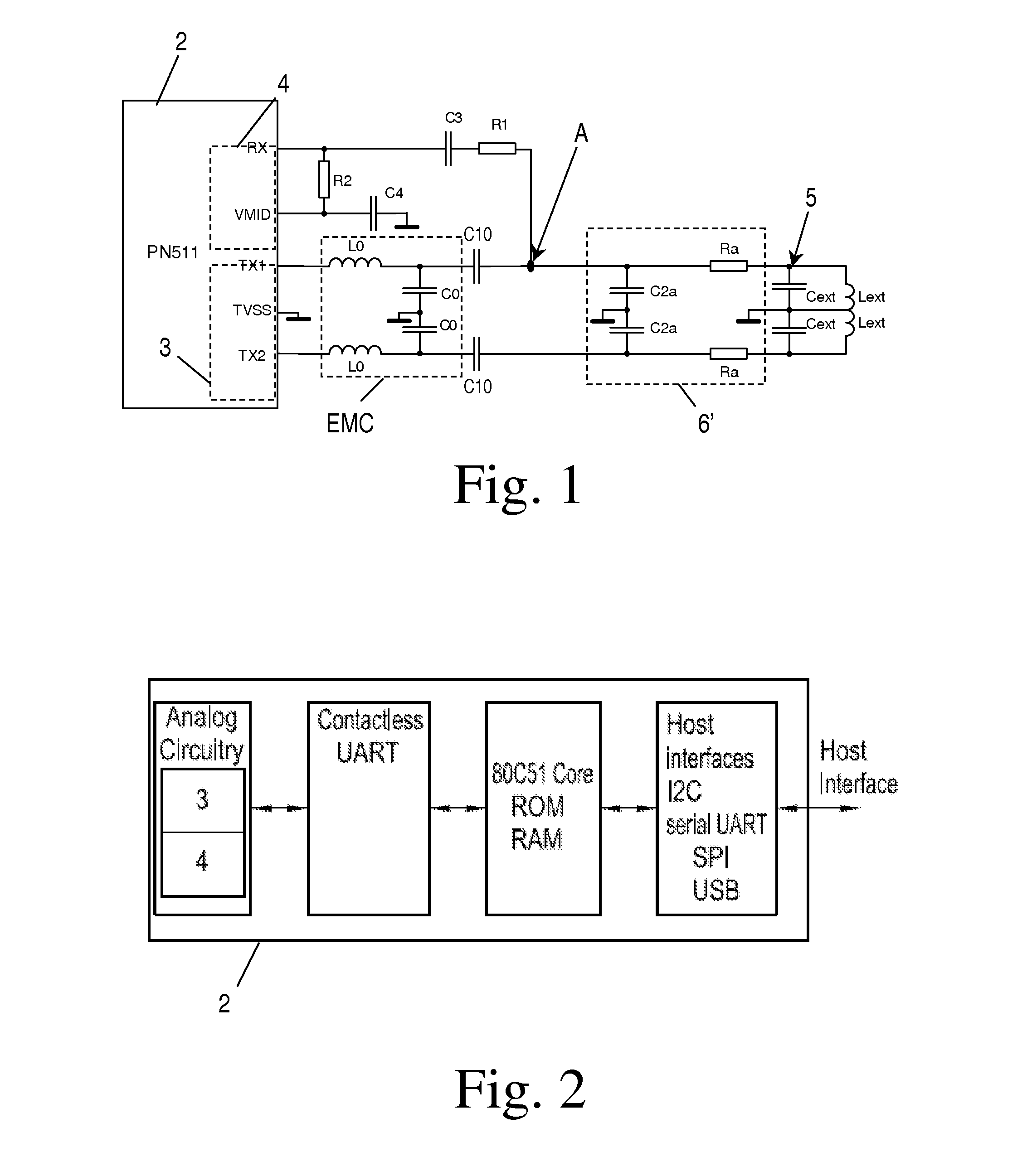
FIELD OF THE INVENTION[0001]The invention relates to a transceiving circuit for contactless communication comprising transmitter means being adapted to generate an electromagnetic carrier signal and to modulate the carrier signal according to transmitting data, and an antenna being connected to and driven by the transmitter means with the modulated carrier signal.[0002]The invention further relates to an NFC device or an RFID reader / writer device.BACKGROUND OF THE INVENTION[0003]FIG. 1 shows a prior art implementation of a transceiving circuit for contactless communication. This transceiving circuit employs an integrated near field communication transmission module 2, e.g. type no. PN5xx, e.g. type no. PN511 or PN512 manufactured by NXP Semiconductors, and external passive electronic components. The transmission module 2 is integrally equipped with transmitter means 3 being adapted to generate an electromagnetic carrier signal, to modulate the carrier signal according to transmittin...

Claims


Application Information

Patent Timeline
IPC IPC(8): H01Q1/50
CPCG06K19/0723G06K19/07749G06K19/0726
Inventor MERLIN, ERICH
Owner QUOTAINNE ENTERPRISES
Learn More