Lighting Device for Liquid Crystal Screen

a liquid crystal display and light source technology, applied in the direction of optics, instruments, non-linear optics, etc., can solve the problems of power source, high electrical consumption, and need, and achieve the effect of improving the degree of light transmission, and reducing the electrical consumption of liquid crystal displays

Inactive Publication Date: 2011-02-24
COMMISSARIAT A LENERGIE ATOMIQUE ET AUX ENERGIES ALTERNATIVES
View PDF8 Cites 2 Cited by
  • Summary
  • Abstract
  • Description
  • Claims
  • Application Information

AI Technical Summary

Benefits of technology

[0006]In the invention, a technical solution has been sought making it possible to improve the degree of light transmission, so as to reduce the electrical consumption of liquid crystal displays, without degrading their performance notably in terms of luminance.

Problems solved by technology

For these reasons, powerful sources, having high electrical consumption, are necessary for producing high-luminance displays.

Method used


Image

  • Lighting Device for Liquid Crystal Screen
  • Lighting Device for Liquid Crystal Screen
  • Lighting Device for Liquid Crystal Screen

Examples


Embodiment Construction

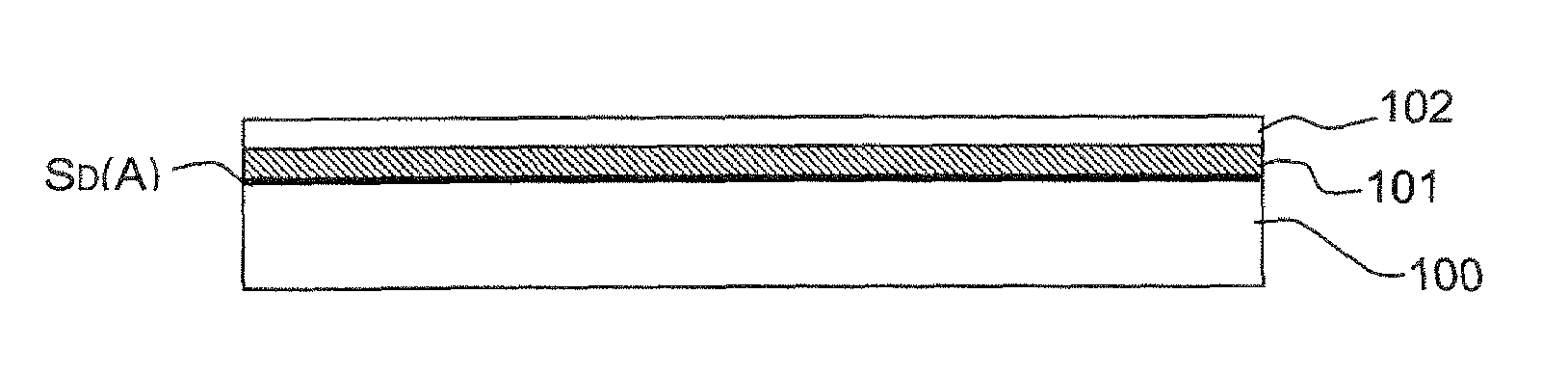
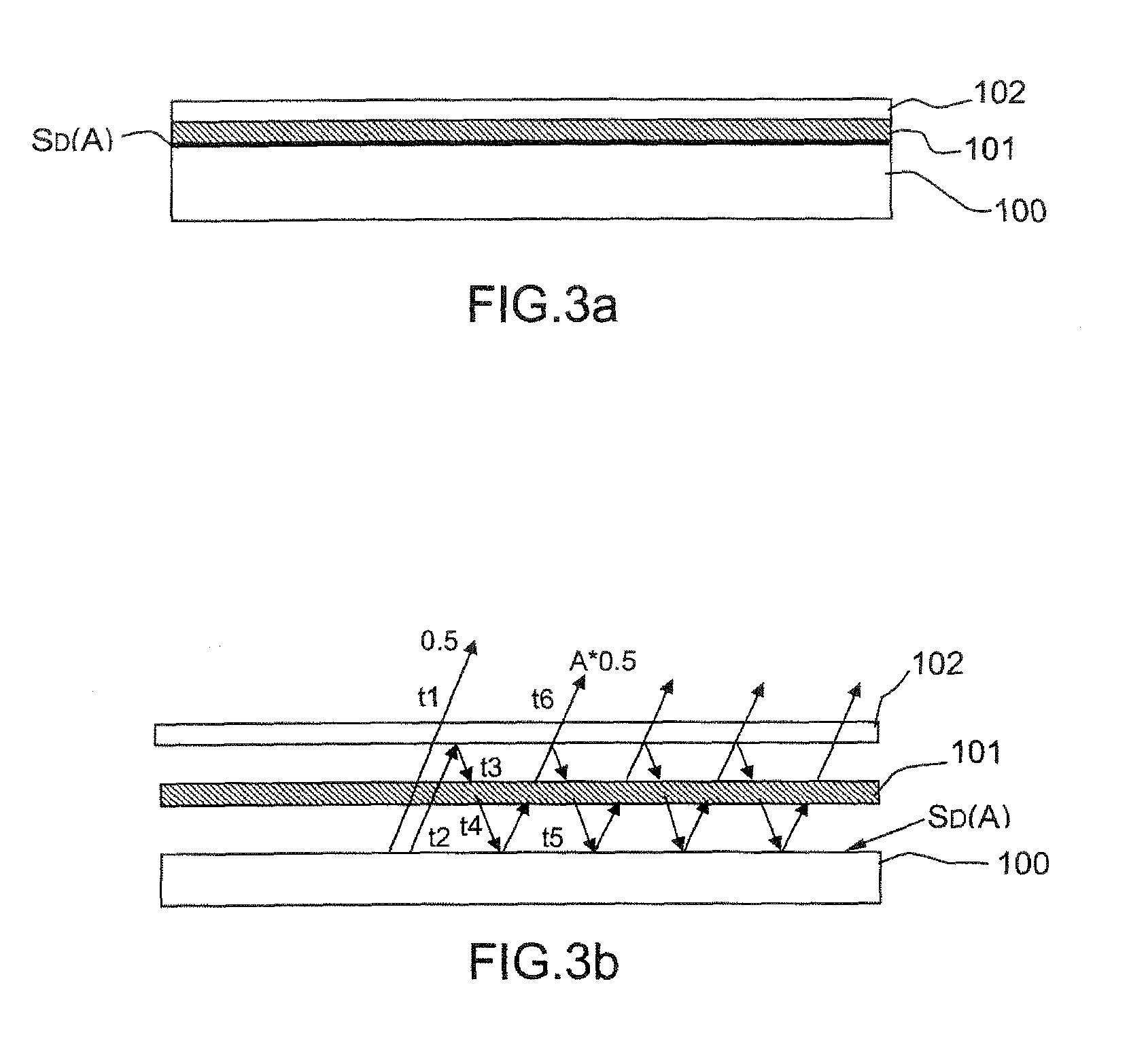
[0025]As illustrated in FIGS. 3a and 3b, a lighting device according to the invention comprises the superposition of an unpolarized extended light source 100, a quarter-wave plate 101 and a reflective polarizer 102.

[0026]In the source, a light emission surface SD(A) is a layer with high albedo A.

[0027]The albedo is the measure of the capacity of a surface to reflect light diffusely (that is to say in all directions in space). It is expressed by a number lying between 0 and 1, corresponding to the ratio of the quantity of light reflected to the quantity of light received: a surface which reflects all the light has an albedo of 1, a surface which absorbs it 100% has an albedo of 0. In the invention, by high albedo A is meant an albedo of greater than or equal to about 0.3 (or indeed greater than or equal to 0.5): at least 30% of the light received is reflected, the remainder being absorbed.

[0028]The principle of the device is more particularly illustrated in FIG. 3b: the unpolarized l...


PUM

PropertyMeasurementUnit
electrical voltageaaaaaaaaaa
electrical voltage Vgaaaaaaaaaa
thickaaaaaaaaaa

Abstract

A lighting device for liquid crystal display provides as output a polarized extended light flux. It comprises a light source 100 comprising a layer with high albedo A on the light emission surface SD(A), on which are stacked a quarter-wave plate 101 and a reflecting polarizer 103. This results in a light transmission gain of the order of 1+A, which makes it possible to produce displays with high luminance and low electrical consumption.
Application to flat-screen displays.

Description

PRIORITY CLAIM[0001]This application claims priority to PCT Patent Application Number PCT / EP2008 / 056808, entitled Lighting Device for Liquid Crystal Screen, filed on Jun. 3, 2008.DOMAIN OF THE INVENTION[0002]The present invention relates to a lighting device for liquid crystal screen, in particular for use in low-consumption flat-screen displays.[0003]The invention relates notably to a lighting device for screens of transmissive type. As illustrated schematically in FIG. 1, these screens comprise in a conventional manner, going from their rear face to their front face, an “entrance” polarizer P1, a first transparent substrate S1 whose internal face bears a network of control electrodes, a thickness of liquid crystal XL, a second transparent substrate S2 whose internal face bears a counter-electrode, and optionally a color filter network, and an “exit” polarizer P2, on the front face. An observer looks at the image which is formed on the front face of such a screen. These screens req...

Claims


Application Information

Patent Timeline
Patent Type & Authority Applications(United States)
IPC IPC(8): G02F1/1335G09F13/04B82Y20/00
CPCG02F1/133536G02F1/133617G02F1/13362H01J63/02G09G3/3406G09G2320/062G02F2001/133507G02F1/133507G02F1/1335G09F13/04
Inventor DIJON, JEANLEROUX, THIERRY
Owner COMMISSARIAT A LENERGIE ATOMIQUE ET AUX ENERGIES ALTERNATIVES
Why Eureka
Try Eureka