Electronic Device With A Flexible Display

a flexible display and electronic device technology, applied in the direction of identification means, electrical apparatus casings/cabinets/drawers, instruments, etc., can solve the problems of display support and/or protection failure, side members undergo substantial mechanical stress, etc., and achieve the effect of simplifying the assembly of the edge protector

Active Publication Date: 2011-02-24
SAMSUNG ELECTRONICS CO LTD
View PDF8 Cites 165 Cited by
  • Summary
  • Abstract
  • Description
  • Claims
  • Application Information

AI Technical Summary

Benefits of technology

[0007]It is found to be advantageous to arrange an edge protector with segments and to provide for cooperation of these segments with a mechanism conceived for spatially ordering the segments in the extended state. It is found that spatially ordered segments not only protect edge portions, but also prevent the flexible display from sagging from a substantially flat plane wherein it is stretched in the extended state. In this way, the segments may add to mechanical stability of the flexible display in its extended state or in its partially extended state. It will be appreciated that it is also possible that the mechanism is arranged for spatially ordering the segments of the edge protector for its collapsed stated. It will further be appreciated that the spatial ordering in the extended state may relate to aligning the segments in a head-to-tail fashion, for example. Preferably, in the head-to-tail order there is substantially no space between a preceding and a following segment. Spatial ordering in the collapsed state may relate to a different or slightly different mutual configuration of the segments, for example by providing a space between a preceding and a following segment so that the edge protector may easily be collapsed without causing deformation or damaging thereof. A preferable embodiment of a collapsed state of the edge protector is a rolled-up configuration.
[0021]It is found to be advantageous to use magnetic means, like small constant magnets, arranged on the individual segments for suitably aligning them in the extended state and upon storage. This embodiment has an advantage in that the magnets provide simple and reproducible means for implementing such alignment. Preferably, the magnets are arranged on a leading edge and a trailing edge of each segment for enabling a generation of the attractive force between a magnet of a preceding segment and a magnet of a following segment. In a particular embodiment, the segments may be symmetrical with respect to a longitudinal axis and may be rotatable about a point positioned on said axis. In this case the magnets may be arranged at both sides of each segment with respect to said axis. It is found to be advantageous to use a V-shaped segments, so that a trailing edge and a leading edge of the segments are V-shaped, whereby a point of rotation of each segment is positioned substantially at an origin of the V-shape. Such cooperation of the magnets with the shape of the segments ensures a further improvement of an efficacy of spatial ordering the segments in the extended state. Preferably, the magnets are arranged substantially symmetrically with respect to the longitudinal axis. This embodiment will be discussed in more detail with reference to FIGS. 5a, 5b.

Problems solved by technology

It is a disadvantage of the known display device in that the side members undergo substantial mechanical stress during a process of extending and collapsing.
This may lead to a material fatigue causing a deformation of the side member leading to a failure in display support and / or protection.

Method used


Image

  • Electronic Device With A Flexible Display
  • Electronic Device With A Flexible Display
  • Electronic Device With A Flexible Display

Examples


Embodiment Construction

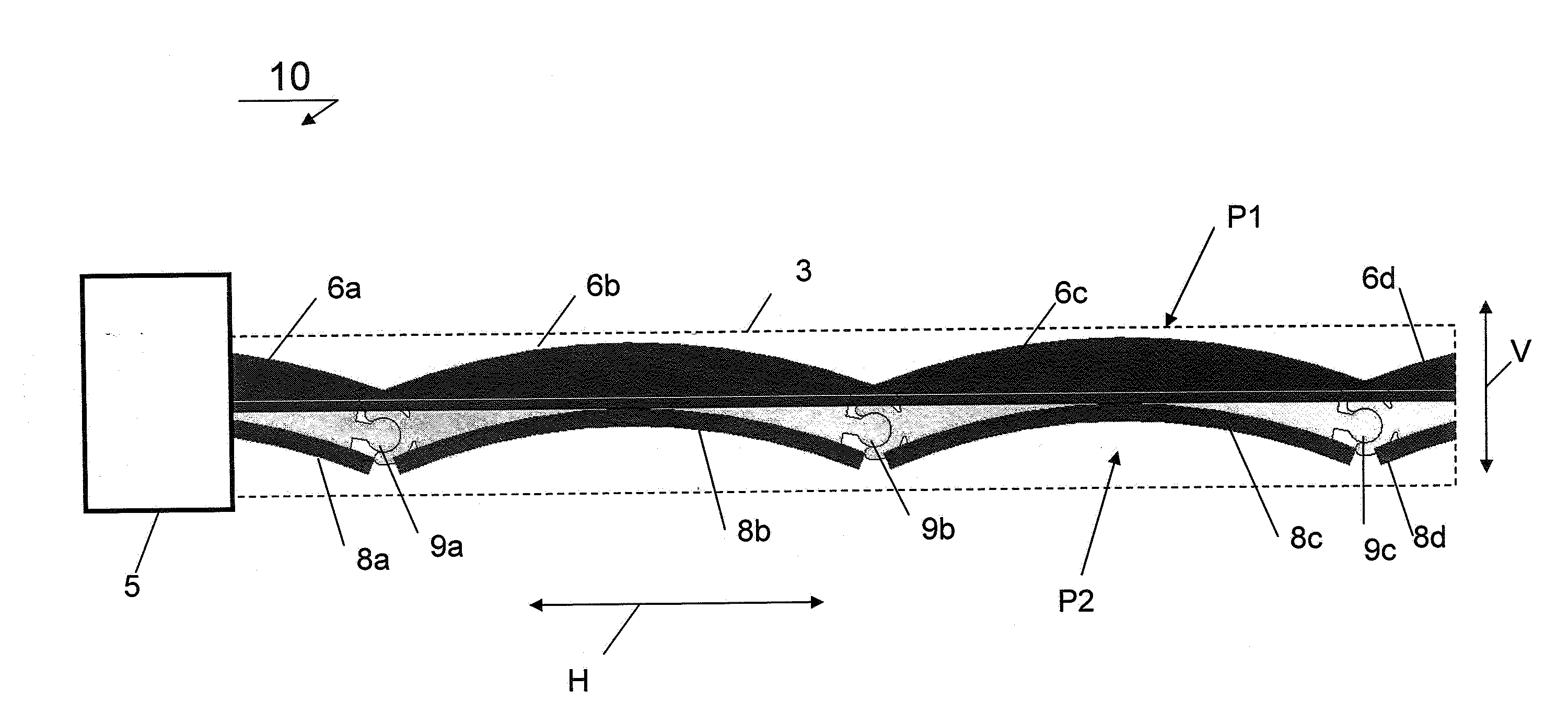
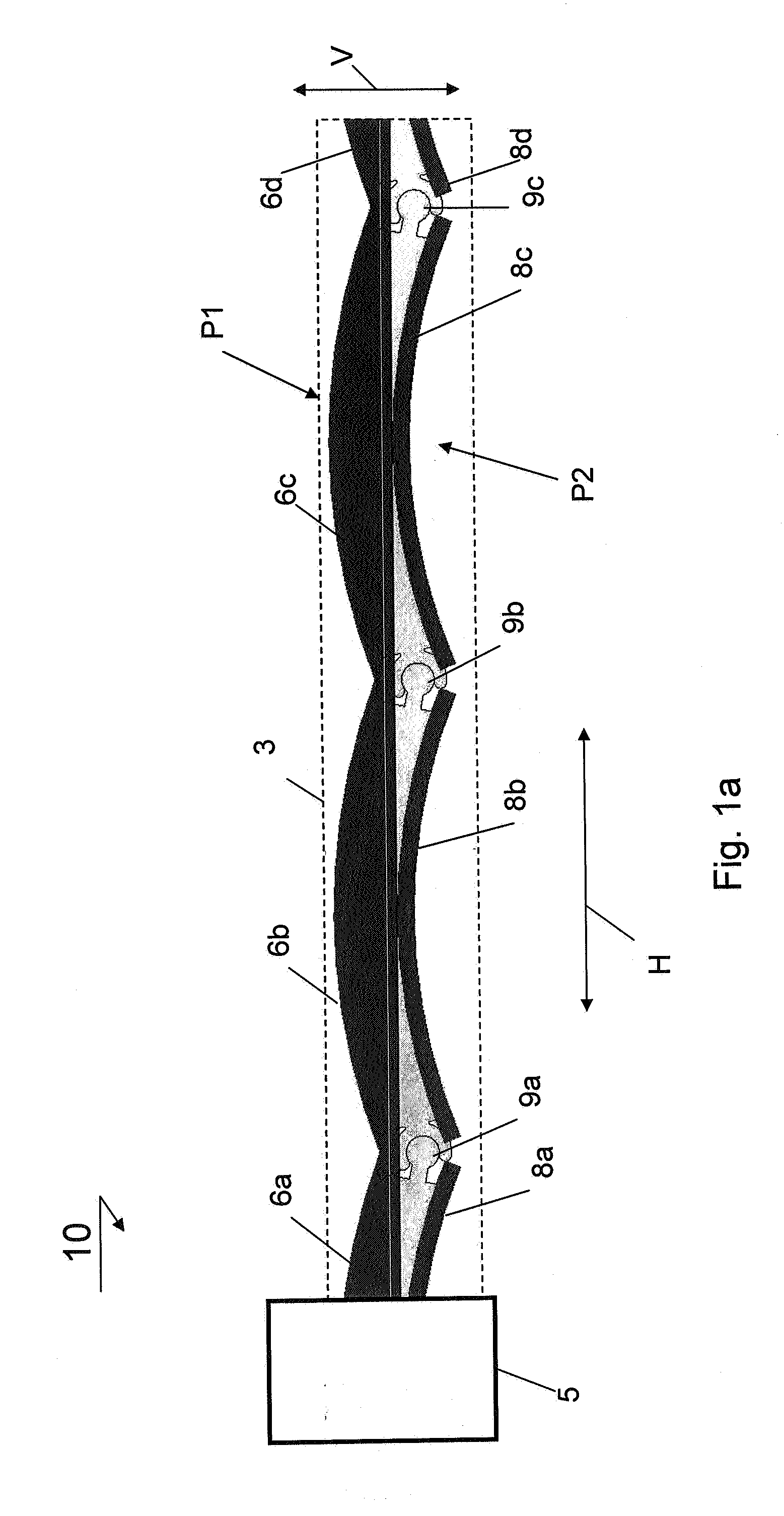
[0030]FIG. 1a presents in a schematic way a detailed view of the edge protector of the electronic device according to the invention in an extended state. FIG. 1a schematically presents a vertically section 10 of an electronic apparatus provided with a flexible display 2, which may be extendable from a housing 5 upon use. It will be appreciated that the flexible display is a structure comprising an active area with a suitable user interface (not shown) surrounded by one or more lateral edge portions 3, which are preferably not used for the user interface. In accordance with the invention, the edge portions 3 are provided with an edge protector having an upper surface P1 and a lower surface P2, said edge protector being comprised of segments 6a, 6b, 6c, 6d, 8a, 8b, 8c, 8d, which may be interconnected by hinges 9a, 9b, 9c, thereby resembling a caterpillar structure provided above and below the edge portions of the flexible display 4. It is noted that either rigid or flexible hinges may...


PUM


Abstract

The invention relates to an electronic apparatus 10 comprising with a flexible display 2, which may be extendable from a housing 5 upon use. In accordance with the invention, the edge portions 3 are provided with an edge protector having an upper surface P1 and a lower surface P2, said edge protector being comprised of segments 6a, 6b, 6c, 6d, 8a, 8b, 8c, 8d, which may be interconnected by hinges 9a, 9b, 9c. The segments of the edge protector are arranged above and below the edge portions of the flexible display 2 and are preferably displaceable during translation of the flexible display from a collapsed to an extended state and back. Preferably, the hinges 9a, 9b, 9c are arranged for enabling a vertical V and / or a horizontal H displacement of the segments. The segmented edge protector is arranged for being moved together with the display and to be stored together with it, so that the segments 6a, 6b, 6c, 6d, 8a, 8b, 8c, 8d substantially do not loose contact with the edge portion during storage.

Description

FIELD OF THE INVENTION[0001]The invention relates to an electronic device comprising a flexible display.BACKGROUND OF THE INVENTION[0002]An embodiment of an electronic device comprising a flexible display is known from WO 2004 / 114259. The known electronic device relates to a display device comprising an extendable, notably rollable display, provided with an extendable side member. The known extendible side member is arranged for providing support and structural rigidity to the flexible display. The known side member is also arranged to provide a solid edge by abutting to the flexible display from a periphery, notably for protecting potentially delicate edge of the display material. In the known display device the display area and the side member conceived to cooperate with the edge portions thereof are stored separately in a housing of the device. In fact, the known display is wound around a suitable roller, whereas the side member is shoved into internal storage channels provided i...

Claims


Application Information

Patent Timeline
Patent Type & Authority Applications(United States)
IPC IPC(8): H05K7/00
CPCG09F9/00G09F9/301G09F11/30G06F1/1652
Inventor VISSER, HENDRIK D.WALTERS, MICHAEL JOHANNES ANNA MARIAHAMERS, JOHANNES CORNELIS ADRIAANHUITEMA, HJALMAR EDZER AYCO
Owner SAMSUNG ELECTRONICS CO LTD
Why Eureka
Try Eureka