
Eureka
For R&D, Eureka makes reading and utilizing patents & technical documents easy.
Eureka AIR
Designed for self-driven R&D workflows. Generate viable solutions, solve complex R&D challenges, empower your innovation with AI.

Eureka Materials
Designed for material experts only. Revolutionize your material R&D, from search, analyze, to developing new materials.

TechResearch
Generate reliable direction feasibility study reports for your R&D in just a few steps.

TechSeek
Discover and master advanced knowledge NOW. Basics, ideas, possibilities, all at once.

TechMind
As an expert in R&D Theories, TechMind can generates customized viable solutions instantly.

TechRisk
Analyze your overall solution with one click, know your potential R&D risks in advance.

TechMonitor
Get weekly tech updates, stay abreast of the latest tech innovations and key insights.
Isochronism corrector for clockwork escapement and escapement provided with such a corrector
- Summary
- Abstract
- Description
- Claims
- Application Information
AI Technical Summary
Problems solved by technology
Method used
Image

Examples
second embodiment
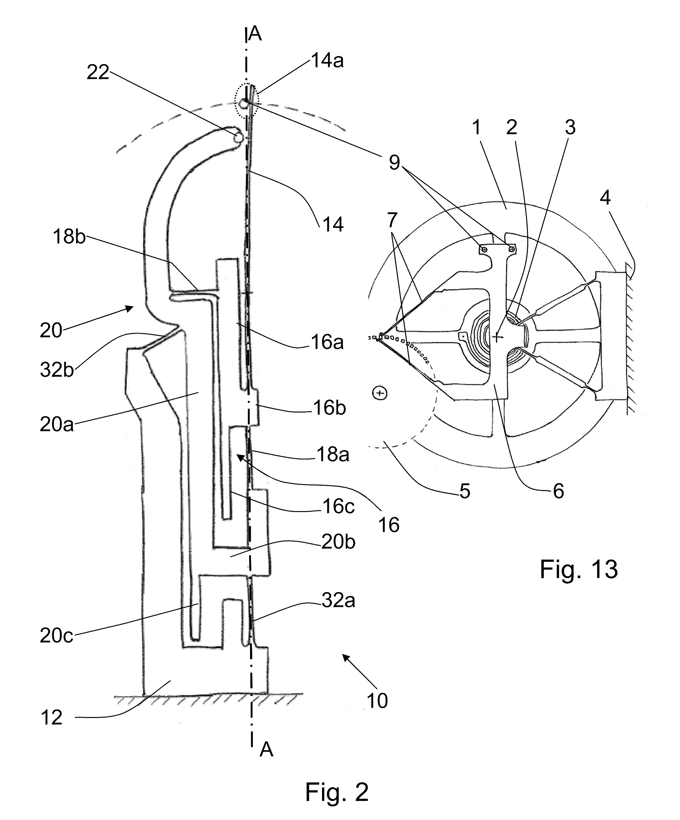
[0047]FIG. 7 proposes the invention, in which the corrector according to the invention has, arranged symmetrically relative to an axis parallel to the axis AA, two correctors as described above, each defining first and second portions. In this figure as in FIG. 13, the pallet 6 includes two pins 9, which are shown in neutral position. The four elastically deformable structures are also presented in neutral position, i.e. not deformed. Preferably, in order to decrease the bulk of such a corrector, the flexible blades 14, the deformable structures and the frame 12 of the first and second portions form a planar piece, preferably made monolithically, by techniques known by those skilled in the art, such as wire electroerosion, photolithography or deep etching.
first embodiment
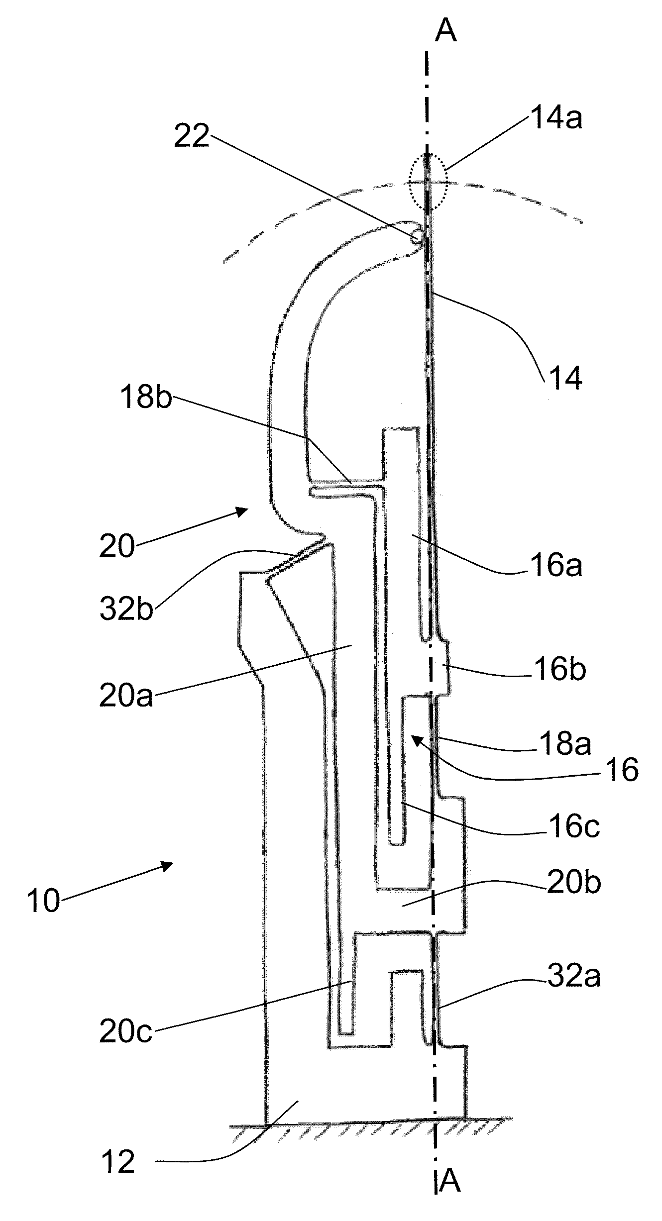
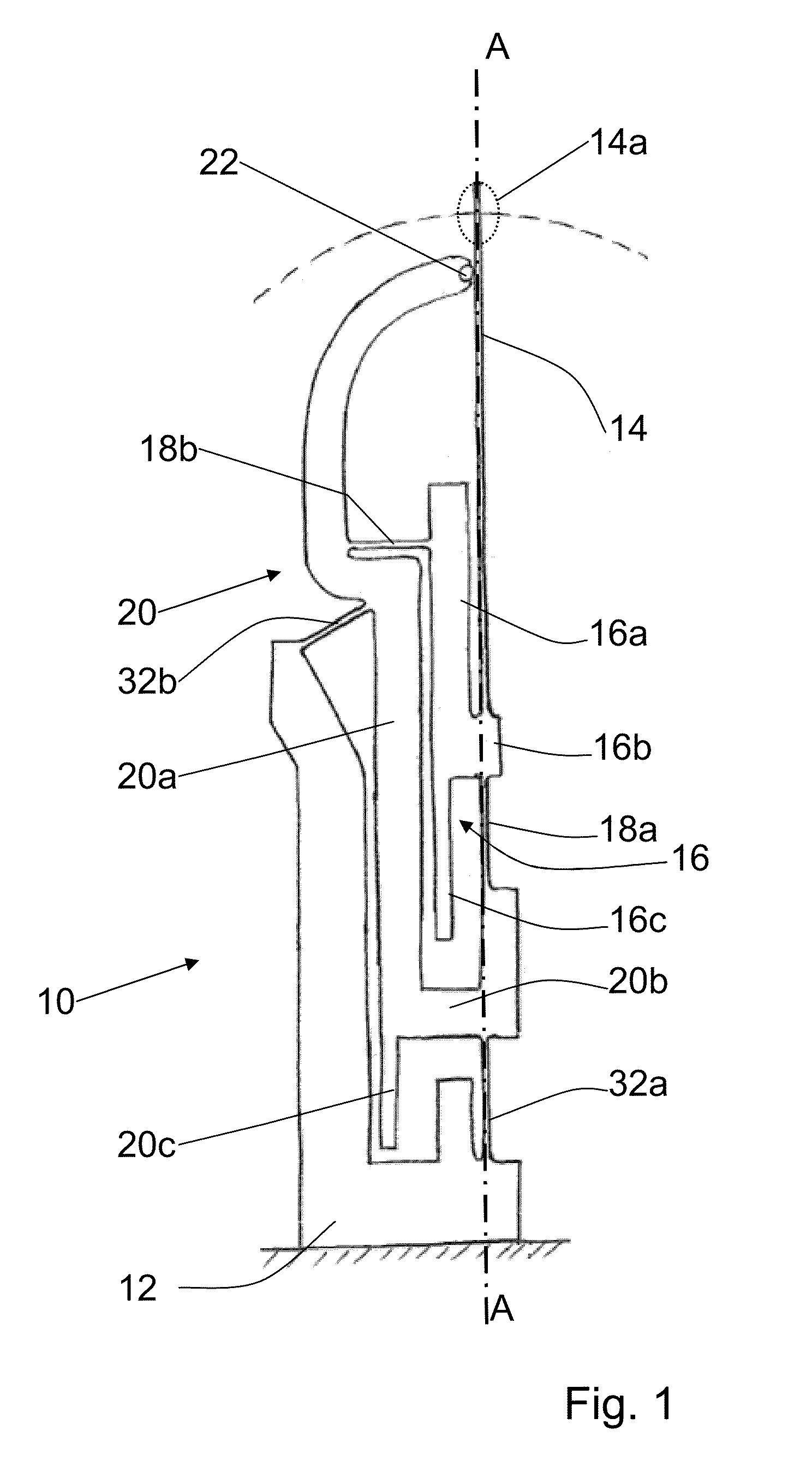
[0048]In a planar structure as proposed in the drawing, the centers of rotation of the deformable structures cannot be combined with the center of rotation of the pallet 6, as for the To best approach these optimal conditions described above in reference to FIGS. 2 and 9, the pivot center of the pallet 6 is positioned at the middle of the segment connecting the pivot centers of the deformable structures, on one hand, of the first portion of the corrector and, on the other hand, of the second portion of the corrector. The blades 14 are arranged as close as possible to a line perpendicular to the path of the oscillator.
[0049]FIG. 8 illustrates a third adjustment that the isochronism corrector, in its simple or symmetrical versions, may present. This adjustment makes it possible to act on the active length of the flexible blade 14 in reference to the oscillator. In other words, one acts on the distance between the embedding point of the flexible blade 14 and the support point of the f...
PUM
 Abstract
Description
Claims
Application Information
 - R&D Engineer
- R&D Manager
- IP Professional
- Industry Leading Data Capabilities
- Powerful AI technology
- Patent DNA Extraction
Browse by: Latest US Patents, China's latest patents, Technical Efficacy Thesaurus, Application Domain, Technology Topic, Popular Technical Reports.
© 2024 PatSnap. All rights reserved.Legal|Privacy policy|Modern Slavery Act Transparency Statement|Sitemap|About US| Contact US: help@patsnap.com