
Controller and Control Techniques for Windfarm

a control system and wind farm technology, applied in the direction of adaptive control, electric generator control, instruments, etc., can solve the problems of affecting the economic benefits of wind farms, and affecting the operation of wind farms. the effect of reducing the fluctuation of electric power supplied and keeping the electric power output constan

Active Publication Date: 2011-02-24
HITACHI LTD
View PDF2 Cites 24 Cited by
  • Summary
  • Abstract
  • Description
  • Claims
  • Application Information

AI Technical Summary

Benefits of technology

[0007]The object of this invention, which has been made to solve the problem as described above, is to provide a technique for suppressing the fluctuation of the electric power generated by a windfarm and maintaining the output level constant.
[0008]In order to solve the above problem, this invention provides a technique for suppressing the fluctuation of the electric power generated by a windfarm and for maintaining the output level constant.
[0021]According to this invention, a technique can be provided which can suppress the fluctuation of electric power supplied from a windfarm and keep the electric power output of the windfarm constant.

Problems solved by technology

Since electricity cannot be stored basically, the amount of its generation must balance the amount of its consumption.
However, as the number of power generation stations increases, the adjustment of the voltage and the frequency of the power system becomes difficult.
For example, there occurs a problem that the capacity of an automatic load frequency control (LFC) procedure becomes deficient when the load becomes lighter.
However, JP-A-2004-301116, which employs the procedure for suppressing the power fluctuation by using such an electric power storage device as accumulator batteries, will cause the entrepreneurs of wind power generation to suffer the burden of cost.

Method used


Image

  • Controller and Control Techniques for Windfarm
  • Controller and Control Techniques for Windfarm
  • Controller and Control Techniques for Windfarm

Examples


Embodiment Construction

[First Mode of Practice]

[0044]The first mode of practice of this invention will be described below with reference to the attached drawings.

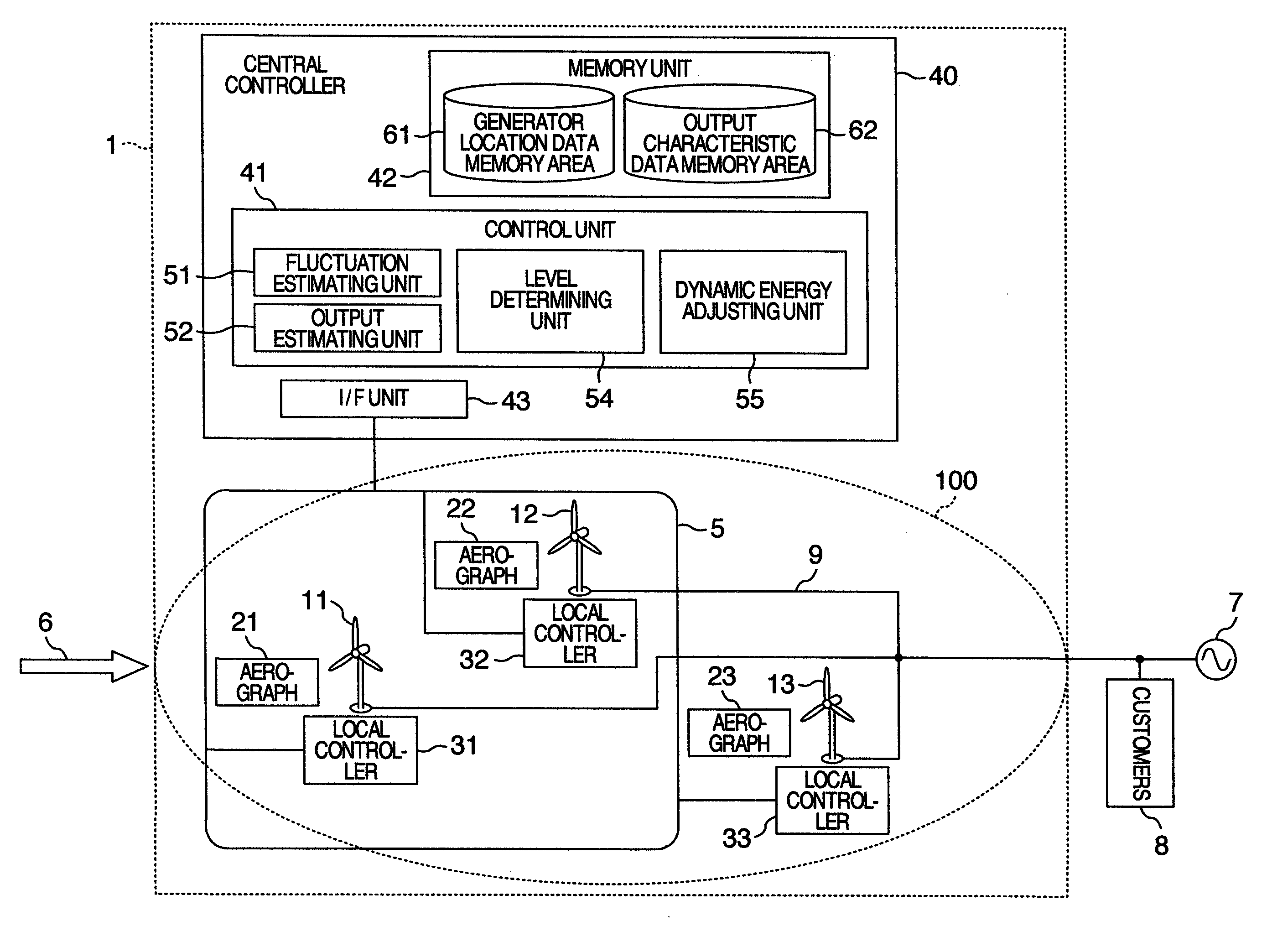
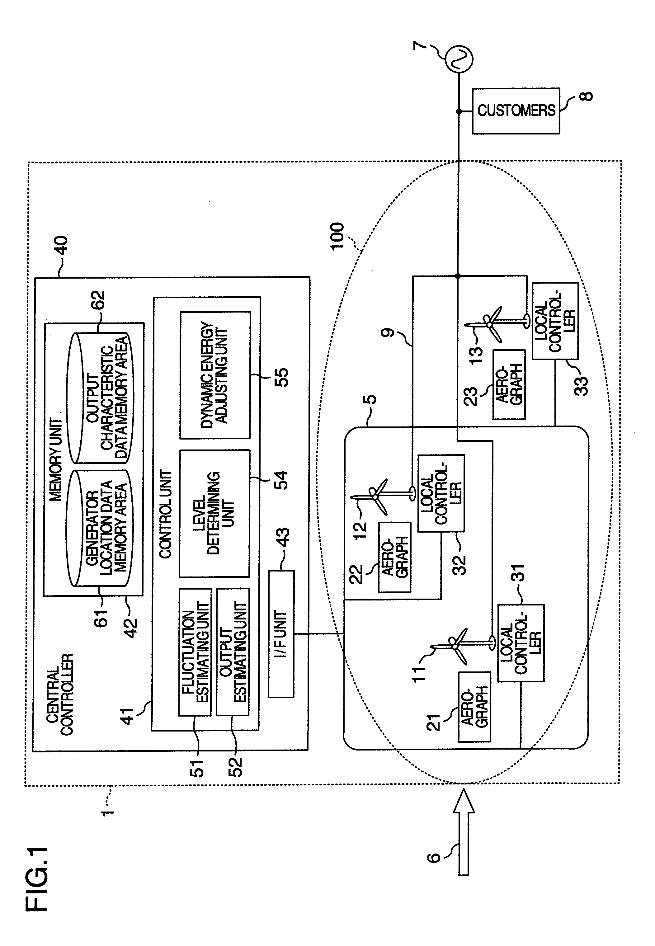
[0045]FIG. 1 shows in block diagram the structure of a windfarm control system according to this invention.

[0046]A windfarm control system 1 consists mainly of a windfarm 100 including plural wind power generators and a central controller 40 for administrating the windfarm in a concentrated manner.

[0047]As shown in FIG. 1, the windfarm 100 comprises wind power generators 11, 12, 13; aerographs 21, 22, 23 disposed close to and electrically connected with the wind generators 11, 12, 13 and designed to measure at least the wind velocity and the atmospheric pressure; local controllers 31, 32, 33; and a communication network 5 for connecting the local controllers 31, 32, 33 with the central controller 40.

[0048]Regarding each of the wind power generators 11, 12, 13, both the rotational speed and the blade pitch of the windmill are variable and controll...


PUM


Abstract

The disclosed windfarm control system comprising a windfarm and a central controller; the windfarm including plural wind power generators whose rotational speeds are variable, plural aerographs disposed in the vicinity of the wind power generators to measure the directions and powers of the wind at the sites of the generators, and plural local controllers disposed in the vicinity of the wind power generators to control the output of the wind power generators by controlling the rotational speeds of the generators; wherein the central controller calculats the control level which maintains the output of the windfarm constant for a predetermined time period and instructs the local controllers to control the rpm's of the wind power generators in accordance with the control level.

Description

BACKGROUND OF THE INVENTION[0001]This invention relates to a system for controlling a windfarm, and an apparatus and a method for controlling a windfarm.[0002]Recently, there has been an increasing tendency for the introduction of wind power generation as a countermeasure against global warming. From the viewpoint of cost effect, the wind power generation finds its most prevalent form of practice in the “windfarm” wherein plural wind power generators are distributed in a specific area and all the generators are administrated together by a central station.[0003]Since electricity cannot be stored basically, the amount of its generation must balance the amount of its consumption. If the balance between these amounts collapses, the frequency of the generated power will fluctuate. In the case of the wind power generation, whose power output fluctuates depending on the weather condition, the frequency of the output power is maintained constant by causing the amount of power generated by t...

Claims


Application Information

Patent Timeline
IPC IPC(8): G06F1/26F03D9/20F03D9/25
CPCF03D7/0272F03D7/028F03D7/047F03D7/048Y02E10/725F05B2270/32F05B2270/321F05B2270/404Y02E10/723F05B2260/821Y02E10/72
Inventor KONDO, SHINICHIONO, YASUNORIUCHIYAMA, NORIYUKIICHINOSE, MASAYAMATSUTAKE, MITSUGUAIHARA, TAKASHI
Owner HITACHI LTD
Learn More