Optical connector cleaning tool

Active Publication Date: 2011-03-03
NTT ADVANCED TECH
View PDF1 Cites 83 Cited by
  • Summary
  • Abstract
  • Description
  • Claims
  • Application Information

AI Technical Summary

Benefits of technology

[0009]In the present invention, when an operator holds the slider with hand, brings the distal end of the cleaning pin into contact with the connection surface (ferrule end face) of an optical connector, and moves the slider forward against the slider return spring in this state, the guide projection moves in the spiral groove and presses the groove wall, thereby converting the linear motion of the slider into the rotation of the body by the cam action. When the body rotates, the rotary pod and cleaning pin rotate together. Therefore, the cleaning thread guided to the distal end face of the cleaning pin cleans the connection surface of the optical connector. Since the distal end face of the cleaning pin is pressed against the connection surface of the optical connector, the position of the distal end face remains unchanged even when the body, rotary pod, and cleaning pin rotate, and only the slider moves forward by a predetermined distance to rotate the body, rotary pod, and cleaning pin through a predetermined angle. The rotary pod and body give tension to the cleaning thread by rotating around the supply reel and take-up reel. Accordingly, the cleaning thread is supplied from the supply reel and g

Problems solved by technology

If the ferrule end faces of the optical connectors, particularly, those end faces (connection surfaces) of the optical fibers which are leveled with the coupling end faces of the co

Method used


Image

  • Optical connector cleaning tool
  • Optical connector cleaning tool
  • Optical connector cleaning tool

Examples


second embodiment

[0083]the present invention will be explained below with reference to FIGS. 7 to 24.

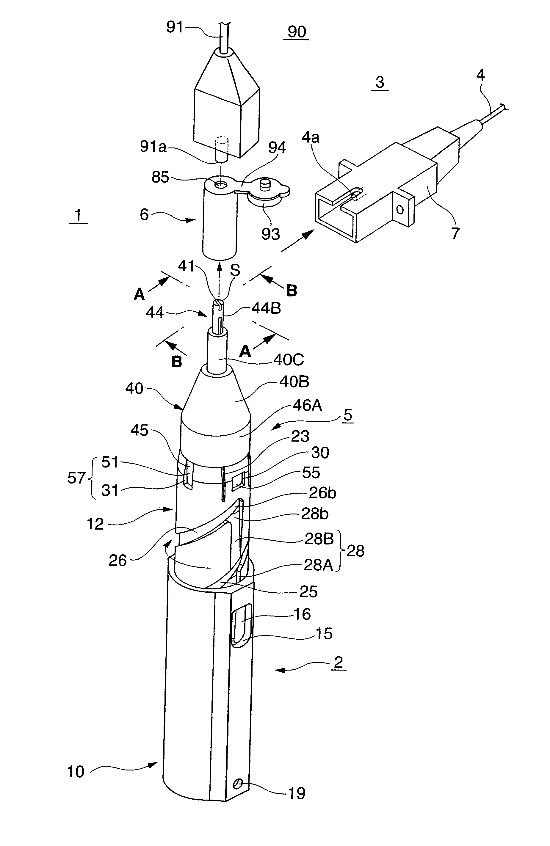
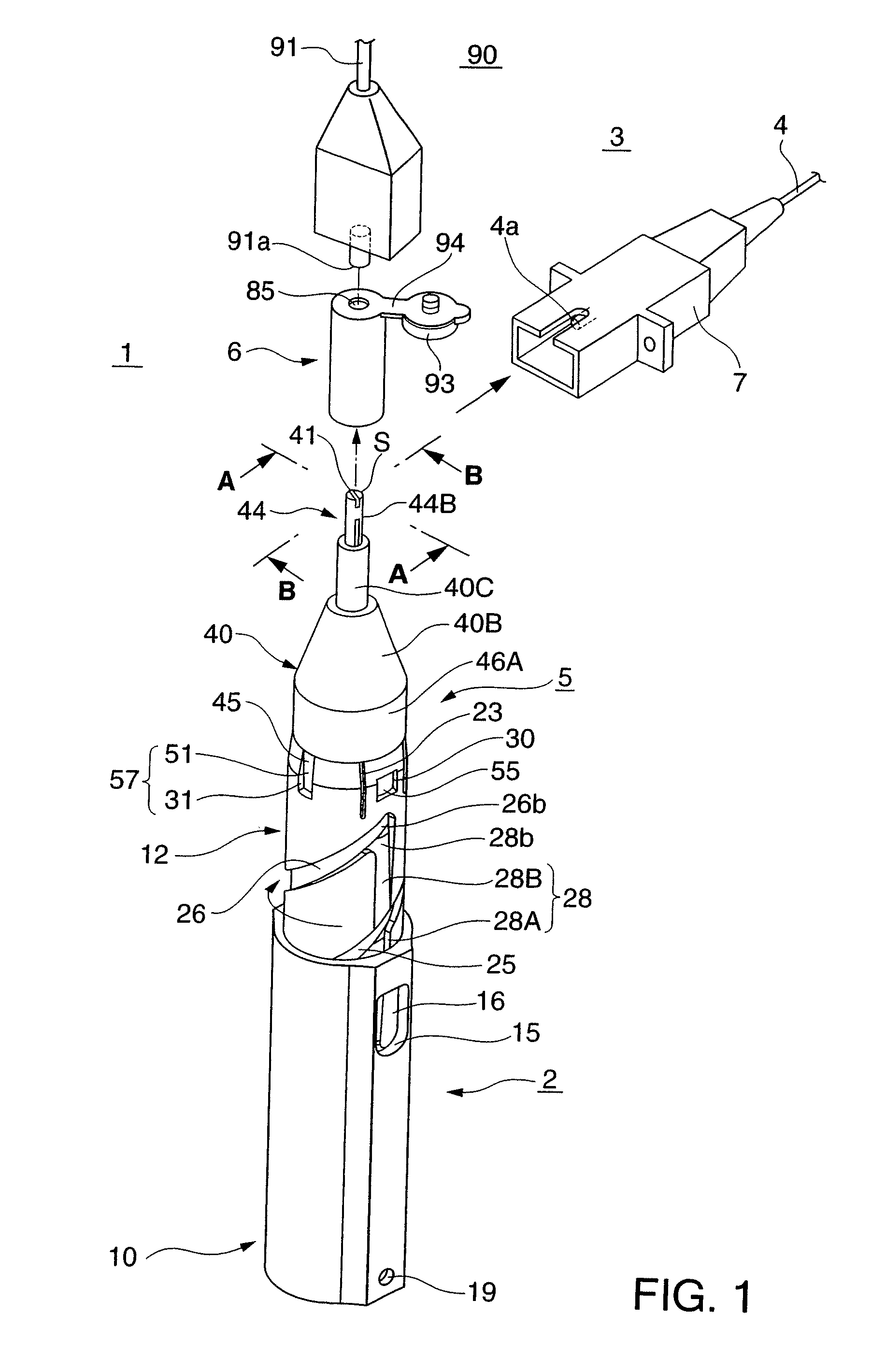
[0084]An optical connector cleaning tool 100 according to this embodiment is applied to cleaning of an SC or FC type optical connector 3 (e.g., a connector defined by JIS C 5973 or 5970) in which the outer diameter of a ferrule 4 is 2.5 mm. Big differences from the optical connector cleaning tool 1 disclosed in the first embodiment described above are that the maximum rotational angle of a rotary pod 40 is 180°, and that a cleaner 5 has a guide portion 101 and thread slack preventing mechanism 102. Accordingly, arrangements different from the above-mentioned first embodiment will mainly be explained, the same reference numerals denote almost the same constituent members and portions, and a repetitive explanation will be omitted.

[0085]Referring to FIGS. 7 to 11, the optical connector cleaning tool 100 includes a holder 2, the cleaner 5, a cap 6, the guide portion 101, and the thread slack preventing m...

first embodiment

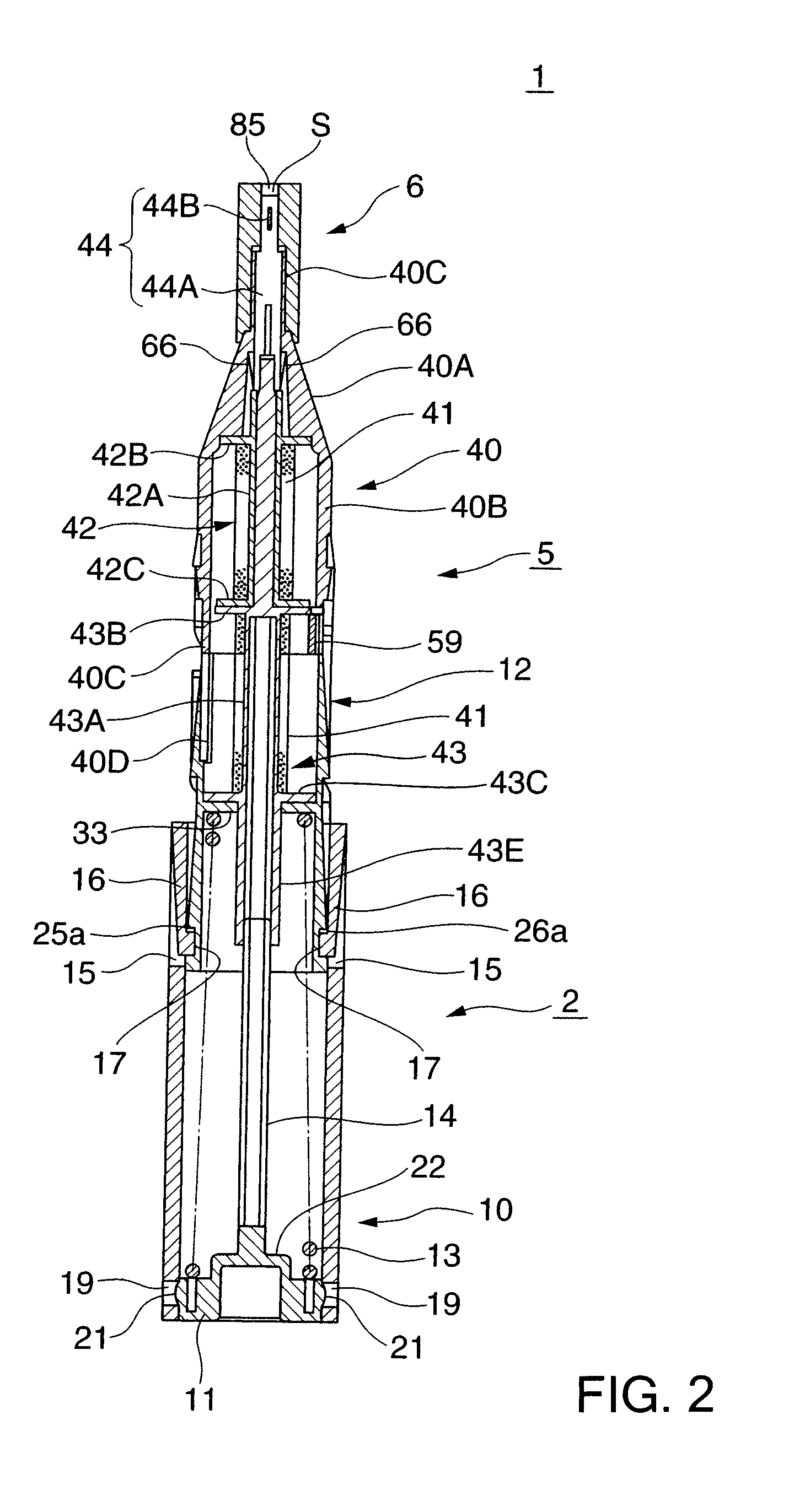
[0086]Similar to the first embodiment described above, the holder 2 includes a slider 10, a lid 11 that closes the rear-end opening of the slider 10, a body 12 partially accommodated in the slider 10, a slider return spring 13, and a shaft 14.

[0087]Elastic pieces 16 of the slider 10 are thin and long plate-like pieces each having two side edges separated from the slider 10 and two ends supported by it. A guide projection 17 is integrally formed on the center of the back surface of each elastic piece 16.

[0088]An annular groove 104 into which the cap 6 is to be detachably inserted is formed in the back surface of the lid 11.

[0089]The body 12 is integrally formed by a resin material, and spiral grooves 25 and 26 and straight grooves 27 and 28 with which the guide projections 17 of the slider 10 can engage are formed in the outer circumferential surface of the body 12. Since the spiral grooves 25 and 26 are formed within the angular range of 180° in the outer circumferential surface of ...

fourth embodiment

[0123]FIG. 26 is a perspective view of the main parts of a cleaning pin according to the present invention. FIG. 27 is a sectional view of the main parts of the cleaning pin. In this embodiment, a head 44D is integrally formed at the distal end of a thread support portion 44B of a cleaning pin 44. The head 44D has a front surface that forms a flat thread support surface, and is connected to the thread support portion 44B with a neck 44E being formed between them. The neck 44E is elastically deformable and hence can tilt the head 44D in all directions. Also, an outer cylinder 280 made of another member is fitted on the outer circumferential surface of the thread support portion 44B, and an annular gap between the outer cylinder 280 and thread support portion 44B forms a thread passage 281 into which a cleaning thread 41 is to be inserted.

[0124]When using the cleaning pin 44 as described above, the head 44D inclines while ensuring a large contact length between the cleaning thread 41 ...


PUM


Abstract

An optical connector clearing tool (1) includes a holder (2), cleaner (5), and cap (6). The holder (2) includes, e.g., a cylindrical slider (10), a cylindrical body (12) installed to be rotatable and movable in the axial direction with respect to the slider (10), and a slider return spring (13) which biases the body (12) forward to return the slider (10) to the initial position. The slider (10) has a pair of elastic pieces (16) having guide projections (17). In the outer circumferential surface of the body (12), spiral grooves (25, 26) with which the guide projections (17) engage are formed within the angular range of 360°. When the slider (10) moves forward, the body (12) rotates by the cam action of the guide projections (17) and spiral grooves (25, 26). The cleaner (5) includes, e.g., a cleaning thread (41) accommodated in a rotary pod (40), a supply reel (42), a take-up reel (43), and a cleaning pin (44), and is connected to the body (12). The rotary pod (40) and cleaning pin (44) rotate together with the body (12), and the cleaning thread (41) supplied to the distal end face of the cleaning pin (44) cleans the connection surface of an optical connector. The cleaning thread (41) is supplied from the supply reel (42) and taken up to the take-up reel (43) by being given tension by the rotation of the cleaner (5).

Description

TECHNICAL FIELD[0001]The present invention relates to an optical connector cleaning tool to be used to clean the connection surface of an optical connector.BACKGROUND ART[0002]Optical connectors for use in optical communication splice optical fibers as they butt each other. If the ferrule end faces of the optical connectors, particularly, those end faces (connection surfaces) of the optical fibers which are leveled with the coupling end faces of the connectors are contaminated, or deposits such as fats and oils or dust stick to the end faces, the insertion loss of the optical connectors increases, and their return loss decreases. Since optical signals cannot normally be transmitted any longer, it is necessary to remove the contamination or deposits by cleaning the connection surfaces as needed.[0003]Conventionally, as an optical connector cleaning tool for cleaning the connection surface of an optical connector as described above, a stick type cleaning tool C including a shaft porti...

Claims


Application Information

Patent Timeline
IPC IPC(8): B08B1/00
CPCG02B6/3866G02B6/3807
Inventor SUGITA, NAOKITSUBAMOTO, MIEKOKONISHI, MASAAKIKOBAYASHI, MASARU
Owner NTT ADVANCED TECH
Why Eureka
Try Eureka