
Circuits and Methods for Calibration of a Motion Detector

Active Publication Date: 2011-03-03
ALLEGRO MICROSYSTEMS INC
View PDF29 Cites 71 Cited by
  • Summary
  • Abstract
  • Description
  • Claims
  • Application Information

AI Technical Summary

Benefits of technology

[0013]The present invention provides a magnetic field sensor that can accurately identify a threshold level associated with a magnetic field signal, accurate for both fast and slow magnetic field signals

Problems solved by technology

Thus, for fast magnetic field signals (e.g., for fast rotating gears), the time available for calibration is small.
In those applications for which the movement or rotation is rapid and the time available for calibration is small, the rotation detector might not calibrate properly, i.e., the threshold might not be properly determined.

Method used


Image

  • Circuits and Methods for Calibration of a Motion Detector
  • Circuits and Methods for Calibration of a Motion Detector
  • Circuits and Methods for Calibration of a Motion Detector

Examples


Embodiment Construction

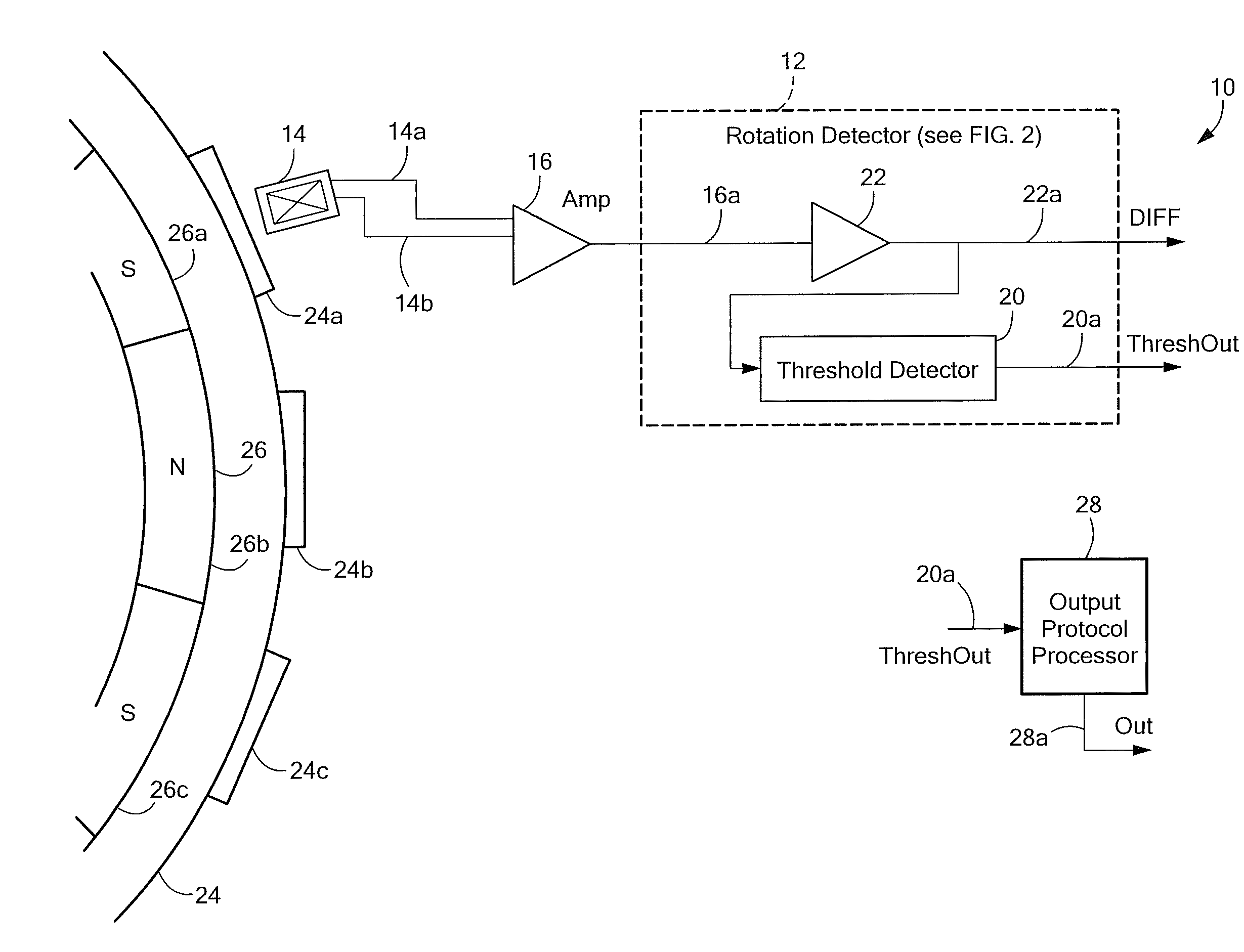
[0030]Before describing the present invention, some introductory concepts and terminology are explained. As used herein, the term “magnetic field sensing element” is used to describe a variety of types of electronic elements that can sense a magnetic field. The magnetic field sensing elements can be, but are not limited to, Hall effect elements, magnetoresistance elements, or magnetotransistors. As is known, there are different types of Hall effect elements, for example, planar Hall elements, vertical Hall elements, circular Hall elements, and Indium antimonide (InSb) sensors. As is also known, there are different types of magnetoresistance elements, for example, anisotropic magnetoresistance (AMR) elements, giant magnetoresistance (GMR) elements, tunneling magnetoresistance (TMR) elements, and magnetic tunnel junction (MTJ) elements.

[0031]As is known, some of the above-described magnetic field sensing elements tend to have an axis of maximum sensitivity parallel to a substrate that...


PUM


Abstract

A circuit to detect a movement of an object has a calibration time period that ends when peak detectors in the circuit stop updating for a predetermined amount of time. A method associated with the circuit is also described.

Description

CROSS REFERENCE TO RELATED APPLICATIONS[0001]Not Applicable.STATEMENT REGARDING FEDERALLY SPONSORED RESEARCH[0002]Not Applicable.FIELD OF THE INVENTION[0003]This invention relates generally to integrated circuits and, more particularly, to integrated circuits for detecting a movement or a rotation of a ferromagnetic object.BACKGROUND OF THE INVENTION[0004]Magnetic field sensors (e.g., rotation detectors) for detecting ferromagnetic articles and / or magnetic articles are known. The magnetic field associated with the ferromagnetic article or magnetic article is detected by a magnetic field sensing element, such as a Hall element or a magnetoresistance element, which provides a signal (i.e., a magnetic field signal) proportional to a detected magnetic field. In some arrangements, the magnetic field signal is an electrical signal.[0005]The magnetic field sensor processes the magnetic field signal to generate an output signal that changes state each time the magnetic field signal crosses ...

Claims


Application Information

Patent Timeline
IPC IPC(8): G01P21/00G01B7/14
CPCG01D5/2448G01D5/12G01D5/125G01D5/244
Inventor FERNANDEZ, DEVONFORREST, GLENN A.
Owner ALLEGRO MICROSYSTEMS INC
Learn More