Feed drive mechanism and connecting assembly thereof
- Summary
- Abstract
- Description
- Claims
- Application Information
AI Technical Summary
Benefits of technology
Problems solved by technology
Method used
Image

Examples
first embodiment
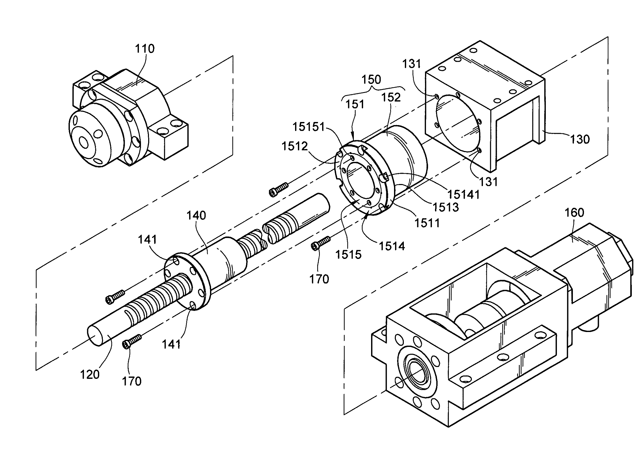
[0043]Referring to FIGS. 3 to 5, a connecting assembly 150 according to the present invention comprises a main body 151 and an outer sleeve 152. The main body 151 has a connecting plate 1511 and an inner sleeve 1518. The connecting plate 1511 further has a first side surface 1512 and a second side surface 1513 opposite to each other. The inner sleeve 1518 is connected to the second side surface 1513 of the connecting plate 1511, and a channel 1519 surrounds an outer side surface of the inner sleeve 1518. The channel 1519 of this embodiment is in a spiral shape, and surrounds the outer side surface of the inner sleeve 1518, such that the channel 1519 is uniformly distributed on the outer side surface of the inner sleeve 1518.
[0044]In addition, the connecting plate 1511 and the inner sleeve 1518 of the main body 151 of the present invention are configured into an integrally formed structure. However, persons skilled in the art may combine the connecting plate 1511 with the inner sleev...
second embodiment
[0054]Referring to FIGS. 9 to 12, a connecting assembly 150 according to the present invention comprises a main body 151 and an outer sleeve 152. The main body 151 has a connecting plate 1511 and an inner sleeve 1518. The connecting plate 1511 further has a first side surface 1512 and a second side surface 1513 opposite to each other. The inner sleeve 1518 is connected to the second side surface 1513 of the connecting plate 1511, and a channel 1519 surrounds an outer side surface of the inner sleeve 1518. The channel 1519 of this embodiment is in a spiral shape and surrounds the outer side surface of the inner sleeve 1518, such that the channel 1519 is uniformly distributed on the outer side surface of the inner sleeve 1518.
[0055]The connecting plate 1511 and the inner sleeve 1518 of the main body 151 of the present invention are configured into an integrally formed structure. However, persons skilled in the art may combine the connecting plate 1511 with the inner sleeve 1518 in a s...
PUM
 Abstract
Description
Claims
Application Information