Smoking Article

a technology of smoking articles and cigarettes, applied in the field of smoking articles, can solve the problems of increased smoke delivery for equivalent puff volumes, no longer providing a low resistance path in the tube, and loss of action, so as to reduce the pressure differential, increase the ventilation level, and reduce the effect of smoking

Inactive Publication Date: 2011-03-03
BRITISH AMERICAN TOBACCO (INVESTMENTS) LTD
View PDF4 Cites 12 Cited by
  • Summary
  • Abstract
  • Description
  • Claims
  • Application Information

AI Technical Summary

Benefits of technology

[0008]Such a filter can help to provide a more consistent level of tar, with a reduced dependency on the smoking regime or how much of the smoking article has already been consumed. For example, in one embodiment, the exit of the tube in the first section is at least partly blocked after a first amount of smoking Consequently more smoke now goes through the remainder of the first filter section (other than the tube), comprising some form of filter material. After a further amount of smoking, the entrance into the tube in the third section is at least partly blocked. More smoke is now routed through the remainder of the third filter section (other than the tube), again comprising some form of filter material. Accordingly, this embodiment provides a graduated and controlled rise in the filtration efficiency of the filter as the smoking article is consumed. Note that the rise in filtration efficiency occurs more rapidly for higher puff volumes and / or puff rates (since in this case the tubes block more quickly). In addition, the rise in filtration efficiency of the filter helps to compensate for reduced filtration by the unburnt tobacco rod itself as the smoking article is consumed.
[0012]Ventilation may be provided around the circumference of the filter in one or more zones. The ventilation zone is preferably located downstream of a potential blockage point. In one embodiment, ventilation holes are provided on the outside of the second and / or third filter section. If the tubes through the first and third sections are centrally located (i.e. coaxial with the smoking article), then initially most of the airflow is along the central axis of the smoking article. However, as the ends of the tubes become at least partly blocked, and the flow of smoke is forced towards the outer portions of the smoking article, this increases the amount of air drawn in through the ventilation holes to dilute the smoke. In addition, the pressure differential, or pressure drop (PD), of the smoking article will increase. The positioning of the ventilation immediately downstream of the blockage points result in increased ventilation levels as the PD of the filter increases.
[0013]In one embodiment, the filter comprises additional pairs of sections in succession along the cylindrical axis of the smoking article after the third section. Each additional pair of sections comprises a first and second additional section. The first additional section includes at least one tube running the length of the first additional section, substantially parallel to the cylindrical axis of the smoking article. The second additional section comprises filter material of substantially higher filtration efficiency than the tube of the first additional section. Increasing the number of filter sections in this manner allows further control over the filter behaviour. For example, if a fourth and fifth filter section are provided analogous to the second and third filter sections, then the tube in fifth filter section will at least partly block some time after the tube in the third filter section becomes at least partly blocked. Such a filter therefore has more gradations in the rise of filter efficiency as respective tubes become blocked.

Problems solved by technology

However, this action is lost as the tobacco rod is burnt to increasingly shorter lengths, resulting in increased smoke delivery for equivalent puff volumes during the latter puffs.
However, as the cigarette warms up, the central tube collapses, and the vacated space is then occupied by expansion of the surrounding cellulose acetate material.
The tube now no longer provides a low resistance path for smoke through the first element, with the smoke having to pass instead through the comparatively high resistance of the cellulose acetate of the first element.

Method used


Image

  • Smoking Article
  • Smoking Article
  • Smoking Article

Examples


Embodiment Construction

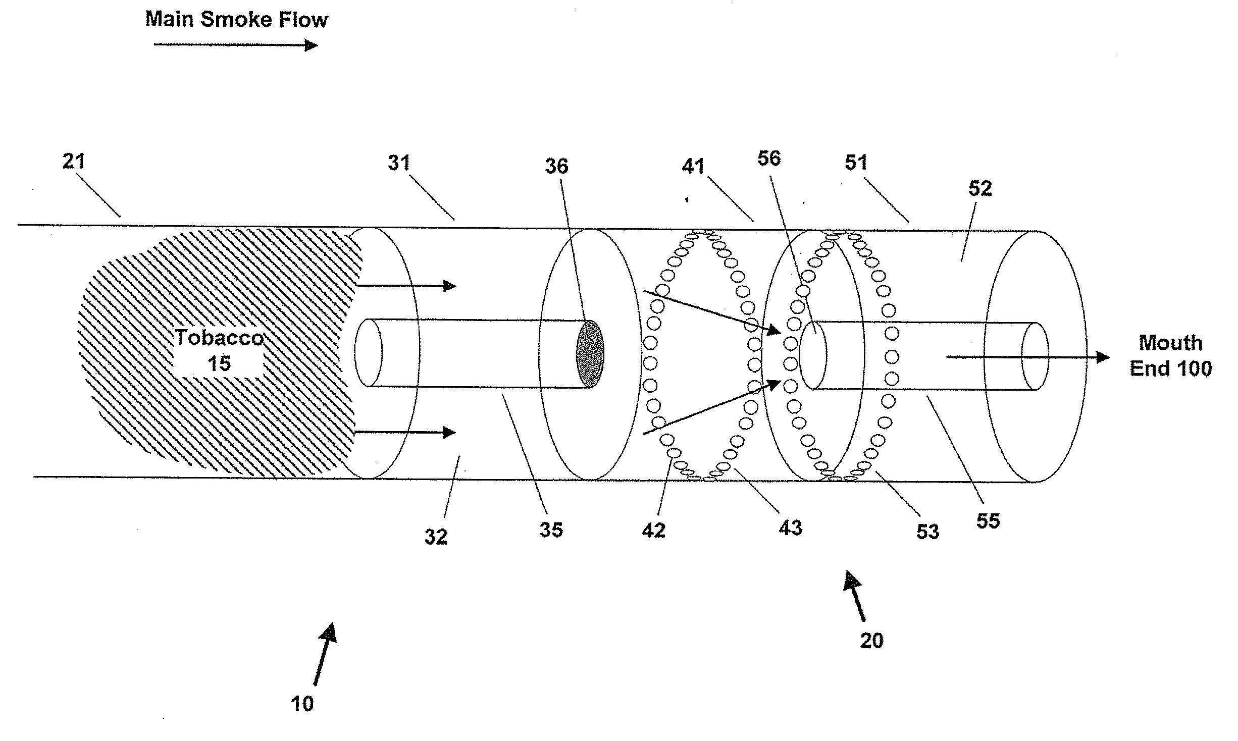
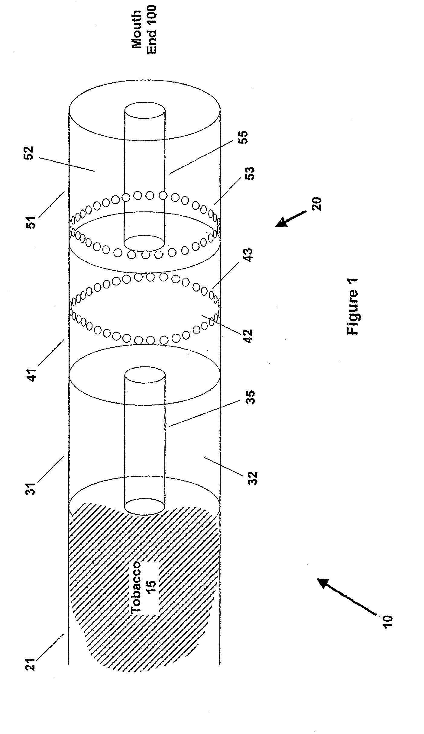
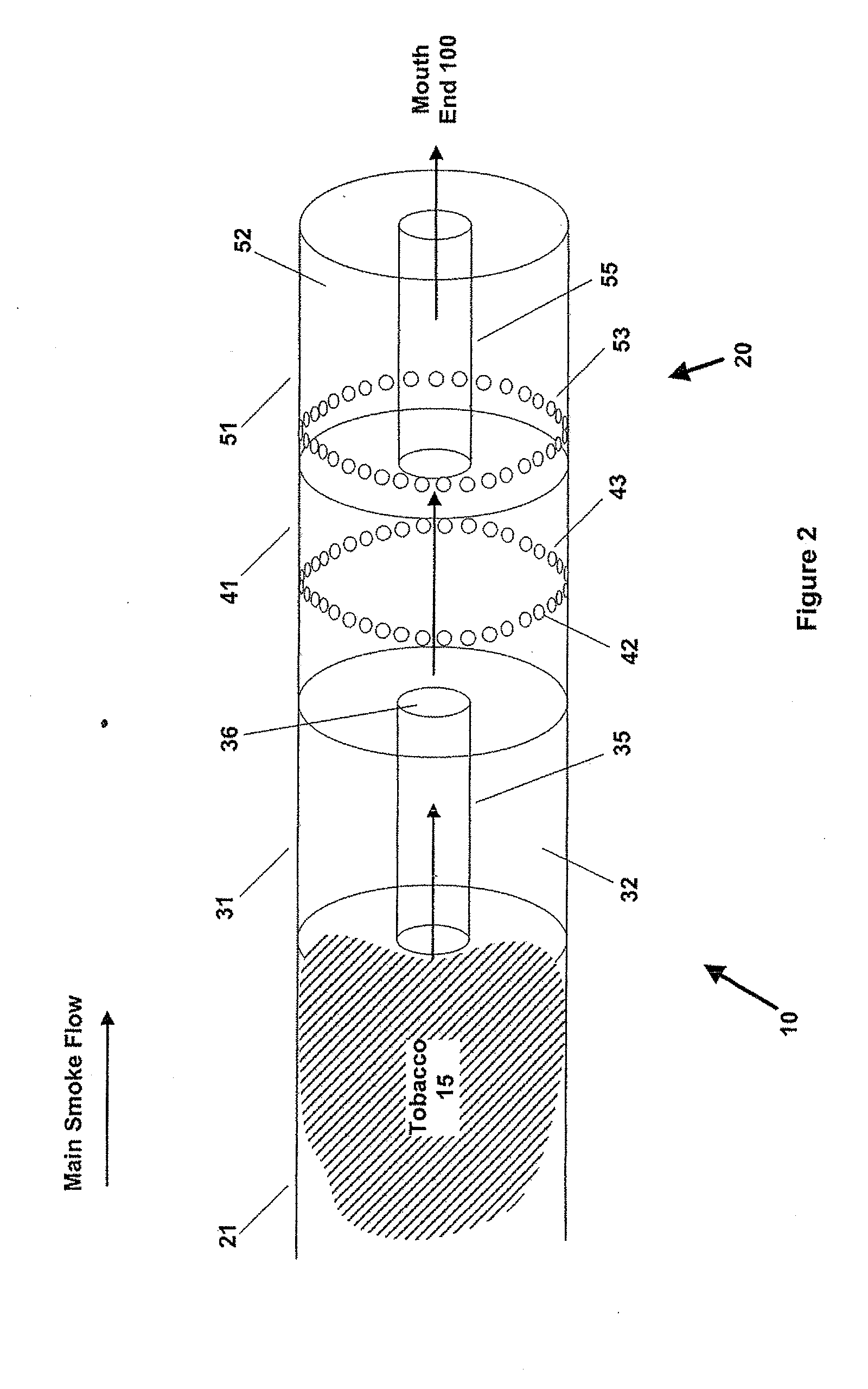
[0020]FIG. 1 is the schematic illustration of a cigarette 10 in accordance with one embodiment of the invention. Cigarette 10 has a generally cylindrical shape, and comprises a tobacco rod 15 (only shown partly in FIG. 1) joined to a filter 20 with an outer wrap 21. The filter is located at the mouth end 100 of the cigarette. The cigarette 10 is lit at the end of the tobacco rod 15 opposite to the mouth end.

[0021]Filter 20 comprises three sections 31, 41, 51 arranged along the cylindrical axis of the cigarette, where each section is cylindrical in shape. Section 31 is adjacent the tobacco rod 15, section 51 is adjacent the mouth end 100, and section 41 is between section 31 and section 51. The configuration of cigarette 10 is therefore determined by a succession of three planes, all perpendicular to the cylindrical axis of the cigarette. The first plane defines the boundary between tobacco rod 15 and the first filter element 31, the second plane defines the boundary between the firs...


PUM


Abstract

A smoking article (10) has a filter (20) located at one end, the filter comprising at least first, second and third sections (34,41,51) disposed in succession along a cylindrical axis of the smoking article. Each of the first (31) and third (51) sections includes at least one tube (35,55) running the length of the respective section, substantially parallel to the cylindrical axis of the smoking article. The second section (41) comprises material of substantially higher filtration efficiency than the tubes (35,55) of the first and third section. Ventilation (43) may be provided around the circumference of the filter in one or more zones.

Description

FIELD OF THE INVENTION[0001]The present invention relates to smoking articles such as cigarettes, and in particular to smoking articles that include a filter.BACKGROUND OF THE INVENTION[0002]When tobacco in a cigarette is burnt as the cigarette is smoked, tar is produced. In recent years, there has been a shift in consumer preference towards lower tar cigarettes. Accordingly, it is desirable to produce a cigarette that delivers less tar to the consumer.[0003]Existing cigarettes have for many years included a filter that can help to reduce tar output. As the cigarette is smoked, the point of combustion moves closer to the filter. When the cigarette is first lit, the rod of unburnt tobacco itself provides a certain amount of filtration action, and can therefore help to reduce tar delivery. However, this action is lost as the tobacco rod is burnt to increasingly shorter lengths, resulting in increased smoke delivery for equivalent puff volumes during the latter puffs. It is also desira...

Claims


Application Information

Patent Timeline
Patent Type & Authority Applications(United States)
IPC IPC(8): A24D3/04
CPCA24D3/043A24D3/04A24D3/0279A24D3/10
Inventor FIEBELKORN, RICHARD
Owner BRITISH AMERICAN TOBACCO (INVESTMENTS) LTD
Why Eureka
Try Eureka