Methods for laser scribing and breaking thin glass
- Summary
- Abstract
- Description
- Claims
- Application Information
AI Technical Summary
Problems solved by technology
Method used
Image

Examples
example 1
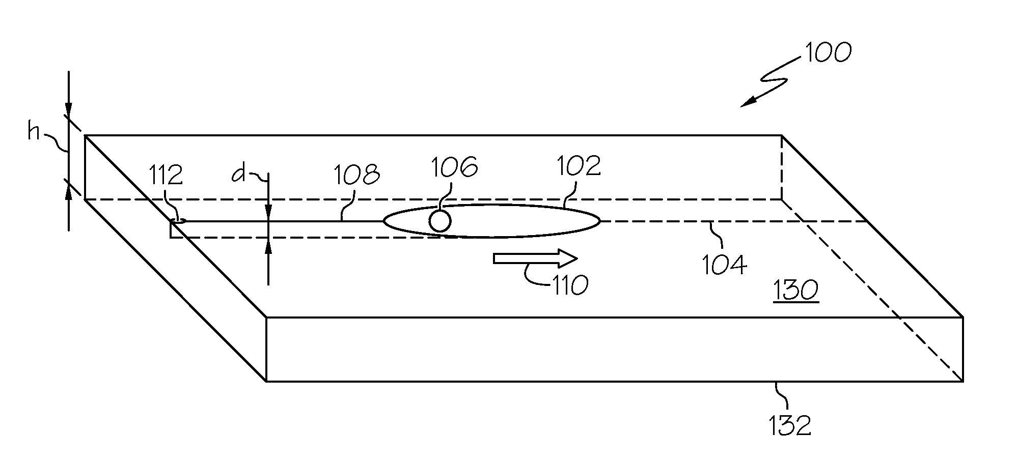
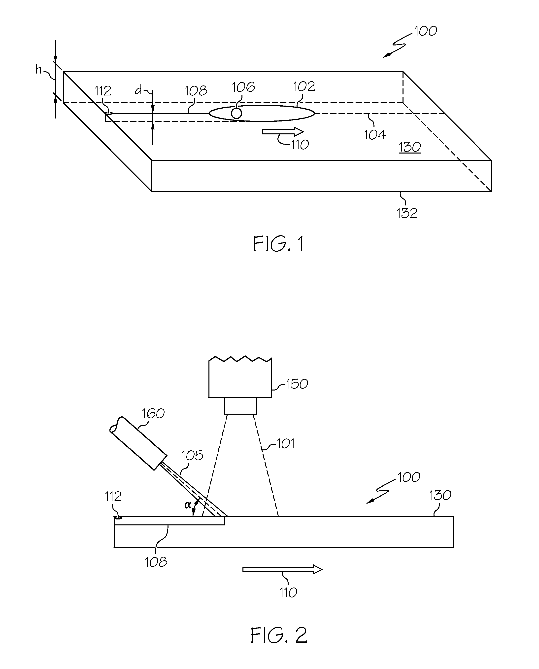
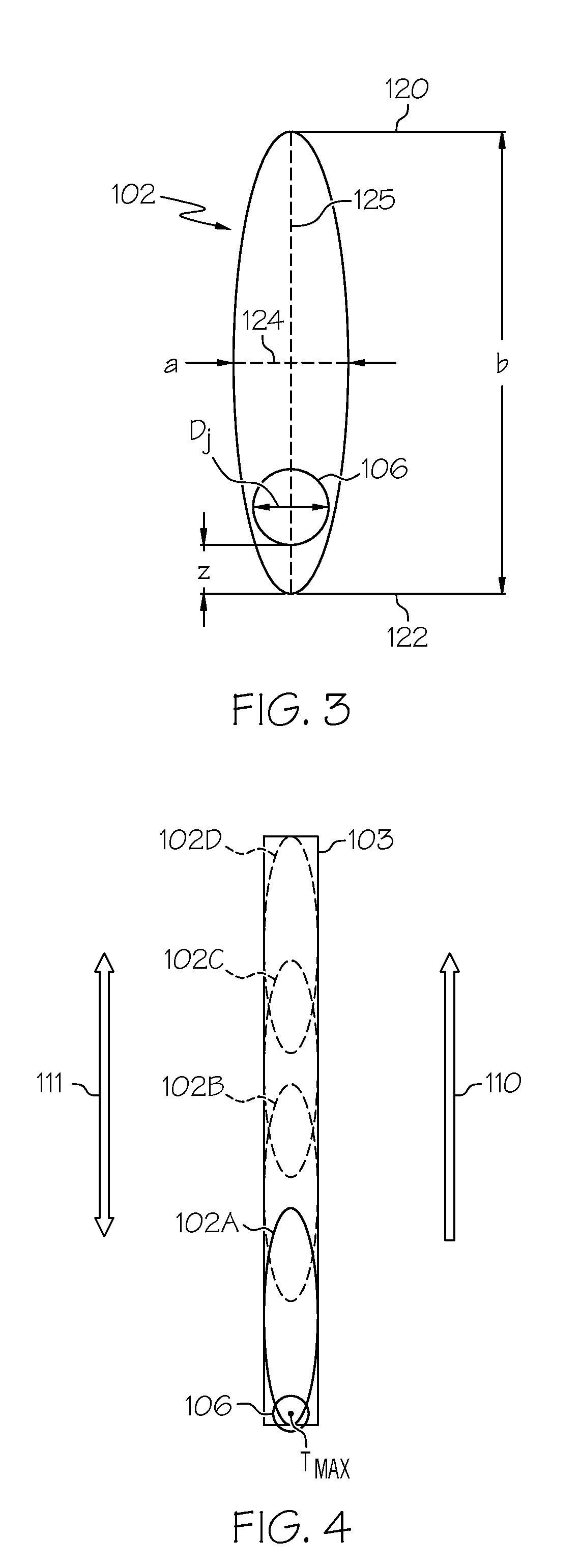
[0060]The beam spot of a CO2 laser with a wavelength of 10.6 μm and a power of 38 Watts was directed onto the surface of a borosilicate glass plate (CTE=32×10−7 / ° C.) with a thickness of 308 μm. The beam spot had a minor axis a=2 mm and a major axis b=24 mm. The beam spot was initially positioned on a defect in the surface of the glass substrate and aligned along a scribe line such that the major axis of the beam spot was collinear with the scribe line. A cooling jet of de-ionized water was directed onto the substrate through a 75 μm orifice of a nozzle at a rate of 8 sccm. The cooling jet had an angle of incidence of 85° relative to the surface of the substrate and formed a cooling spot of approximately 2 mm in diameter on the surface of the glass substrate. The cooling spot was positioned within the elliptical beam spot of the CO2 laser approximately 5 mm from the trailing edge. The elliptical beam spot and cooling jet were advanced along the scribe line at a rate of 4 m / min formi...
example 2
[0061]The beam spot of a CO2 laser with a wavelength of 10.6 μm and a power of approximately 100 Watts was directed onto the surface of a borosilicate glass plate (CTE=32×10−7 / ° C.) with a thickness of 300 μm. The beam spot had a minor axis a=2 mm and a major axis b=24 mm. The beam spot was initially positioned on a defect in the surface of the glass substrate and aligned along a scribe line such that the major axis of the beam spot was collinear with the scribe line. A cooling jet comprising de-ionized water was directed onto the substrate through a 75 μm orifice of a nozzle at a rate of 8 sccm. The cooling jet had an angle of incidence of 85° relative to the surface of the substrate and formed a cooling spot of approximately 2 mm in diameter on the surface of the glass substrate. The cooling spot was positioned within the elliptical beam spot of the CO2 laser approximately 5 mm from the trailing edge. The elliptical beam spot and cooling jet were advanced along the scribe line at ...
example 3
[0062]The beam spot of a CO2 laser with a wavelength of 10.6 μm and a power of 92 Watts was directed onto the surface of an alkali-aluminosilicate glass plate (CTE=91×10−7 / ° C.) with a thickness of 300 μm. The beam spot had a minor axis a=2 mm and a major axis b=24 mm. The beam spot was initially positioned on a defect in the surface of the glass substrate and aligned along a scribe line such that the major axis of the beam spot was collinear with the scribe line. A cooling jet comprising de-ionized water was directed onto the substrate through a 75 μm orifice of a nozzle at a rate of 8 sccm. The cooling jet had an angle of incidence of 85° relative to the surface of the substrate and formed a cooling spot of approximately 2 mm in diameter on the surface of the glass substrate. The cooling spot was positioned within the elliptical beam spot of the CO2 laser approximately 5 mm from the trailing edge. The elliptical beam spot and cooling jet were advanced along the scribe line at a ra...
PUM
| Property | Measurement | Unit |
|---|---|---|
| Thickness | aaaaa | aaaaa |
| Temperature | aaaaa | aaaaa |
| Length | aaaaa | aaaaa |
Abstract
Description
Claims
Application Information