Process for laser scribing

a laser scribing and laser technology, applied in the direction of laser beam welding apparatus, photovoltaics, electrical apparatus, etc., can solve the problems of inability to irradiate through the substrate, panel has to be moved very quickly, add complexity to the control system, etc., to achieve accurate maintenance, significantly slow the overall scribing process, and add time to the overall process

Inactive Publication Date: 2009-07-30
OERLIKON SOLAR AG (TRUEBBACH)
View PDF13 Cites 43 Cited by
  • Summary
  • Abstract
  • Description
  • Claims
  • Application Information

AI Technical Summary

Benefits of technology

[0053]One of the major problems that occurs during the scribing of solar panels is the accurate control of scribe position on the surface of the panel. Most solar panel manufacturing arrangements require three separate sequential laser scribing operations. The positioning accuracy requirements for the scribes in the first layer are much less critical compared to the second and third layer scribes which have to be placed very accurately with respect to the previous scribes. One key advantage of the invention described here where short lengths of scribe lines are created in a series of relatively narrow bands is that an alignment scheme can be readily implemented to measure the position on the panel of existing scribes that are adjacent to the band being scribed. The data gathered is stored and used to correct the scanner trajectory when the measured band is subsequently scribed. In this way the system is continuously measuring the exact position of the previously scribed lines in the next band to be scribed while accurate placement of secondary scribes with respect to primary scribes in each band is being performed. We call this alignment technique “dynamic scribe alignment” (DSA).
[0054]Dynamic scribe alignment (DSA) is implemented in its simplest form by attaching a suitable detector to each scan head. The detector is offset from the beam centre in the direction parallel to the scribe lines by a distance that places it within the width of the adjacent scribe line band. In this position, as the scanner is moved over the surface of the panel or the panel is moved below the scanner, the detector records the position of the scribed lines in the band of lines that will next be processed. When the detector records the presence of a scribed line the encoder position on the gantry or panel stage is recorded as a reference for the scribe line position. This is repeated for all scribe lines in the band. After a complete band has been scribed so that the complete set of data about the position of all scribe lines in the adjacent band has been recorded the data is processed and downloaded to the scanner controller. This data download operation can take place during the time the panel or scanner is moved from the position above the band that has just been laser scribed to the position above the adjacent band that has just been measured. The recorded and processed scribe position data is then used to correct the scanner motion so that the trajectories of the lines scanned are corrected for minor displacements of the previously scribed lines and consequently the spacing between each new line and each previously scribed line can be accurately maintained.
[0055]To allow scribing of lines parallel to either edge of the panel each scanner head needs to have 2 detectors attached to it. The detectors are mounted at 90 degrees to each other with offset directions from the scanner beam centre line parallel to both stage axes. The offset distances from the scanner beam centre line are such as to place the detectors over the adjacent bands in each case.
[0056]This method of “dynamic scribe alignment” (DSA) is very effective as it allows local variations in scribe positions for all lines to be measured and compensated for without significantly slowing the overall scribing process. DSA achieves this as recording of the position of all the sections of scribe lines that already exist in a lower layer film on the panel occurs in one band at the same time as secondary lines are being accurately positioned and scribed in an upper layer in an adjacent band so no significant time is added to the scribing process. The only extra time required is that used to measure the first band of lines In this case it is not possible to scribe lines at the same time so this adds time to the overall process. However, since this alignment pass along the first band can be accomplished at the maximum stage speed permitted, which is significantly faster than the speed used while scribing lines and since there are multiple bands to be scribed, adding one additional pass for gathering the data associated with the line positions in the first band adds a minor amount to the overall time.
[0057]The use of a single scribe line position detector for DSA only permits the accurate alignment and positioning of each subsequent scribe line to a single position on each earlier scribe line. The DSA technique can be considerably improved if two detectors are used on each scan head with both displaced along a line parallel to the scribe line direction and positioned so that one detector records close to one end of the scribe line in the adjacent band and the other detector records close to the opposite end. This means that one detector is displaced about half the scribe line band width from the scanner beam centre position and the separation between detectors is close to the full band width. In this way the two detectors record positions close to the two ends of each scribe line so can be used to detect both the spatial and angular variations of the scribe line sections. By attaching another set of two detectors to the scanner head, arranged at 90 degrees to the first set, the position of the ends of lines in both directions on the panel can be detected and position and angle errors compensated for when the next set of scribes are made.
[0058]A variety of optical based sensors can be used as DSA detectors. The requirement in each case is to detect the location of a line cut in one thin film when overlaid with another. This means that the optical transmission properties of the film at the scribe position usually changes significantly so changes in the optical transmission can be readily measured.

Problems solved by technology

In this case irradiation through the substrate is not possible so all scribing processes require beams incident from the coated side.
In some cases the tools have stationary optics which means the panel has to be moved very rapidly.
Such an approach is acceptable but complex in terms of the number of optics heads and laser beam splitting and balancing requirements.
Having large heavy stage systems moving repetitively backwards and forwards at high speed also leads to unreliability.
This adds complexity to the control system.
The long focal length of the scan lens required leads to limitations to the minimum size of the focal spot that can be created and hence the scribe width that can be made is not as narrow as desired.
It also leads to difficulties placing the scribes accurately as the positioning errors associated with scanner systems scale with the lens focal length.
Both of these are major problems as ideal scribes should be as narrow in width as possible and successive scribes should be as close together as possible as the area between the three scribes does not generate electricity and therefore needs to be minimised.
However, in the secondary and tertiary panel scribing processes where scribes need to be made very close to previous scribes, the bow tie configuration is difficult to implement.
However, simple global distortion correction is not sufficient to allow close and accurate placement of scribes since scribe pitch can become irregular due to errors on the tool that make the first scribe or errors introduced during subsequent panel processing.

Method used


Image

  • Process for laser scribing
  • Process for laser scribing
  • Process for laser scribing

Examples


Embodiment Construction

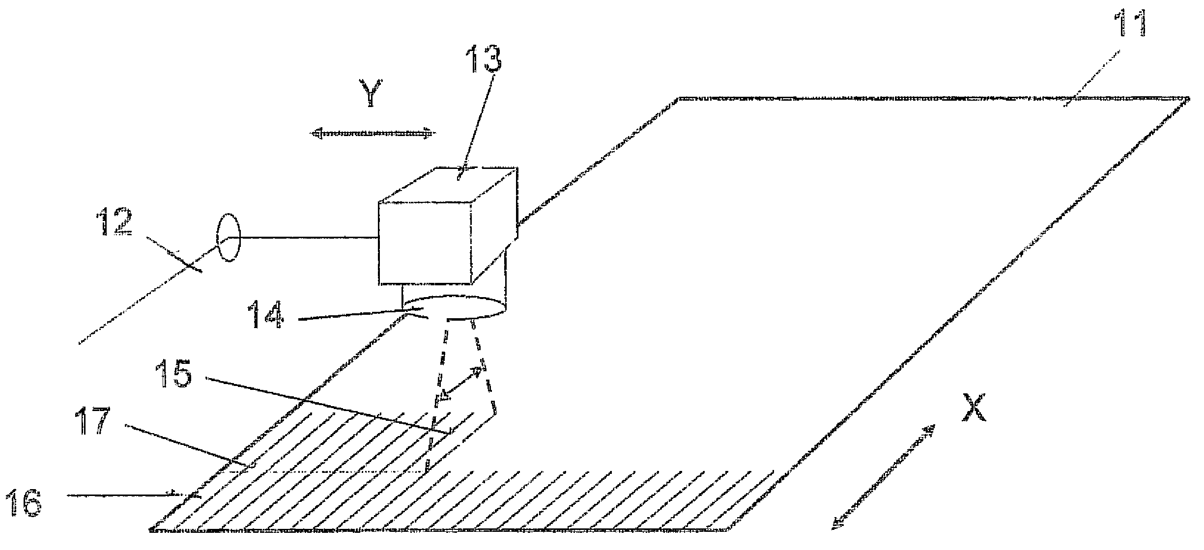
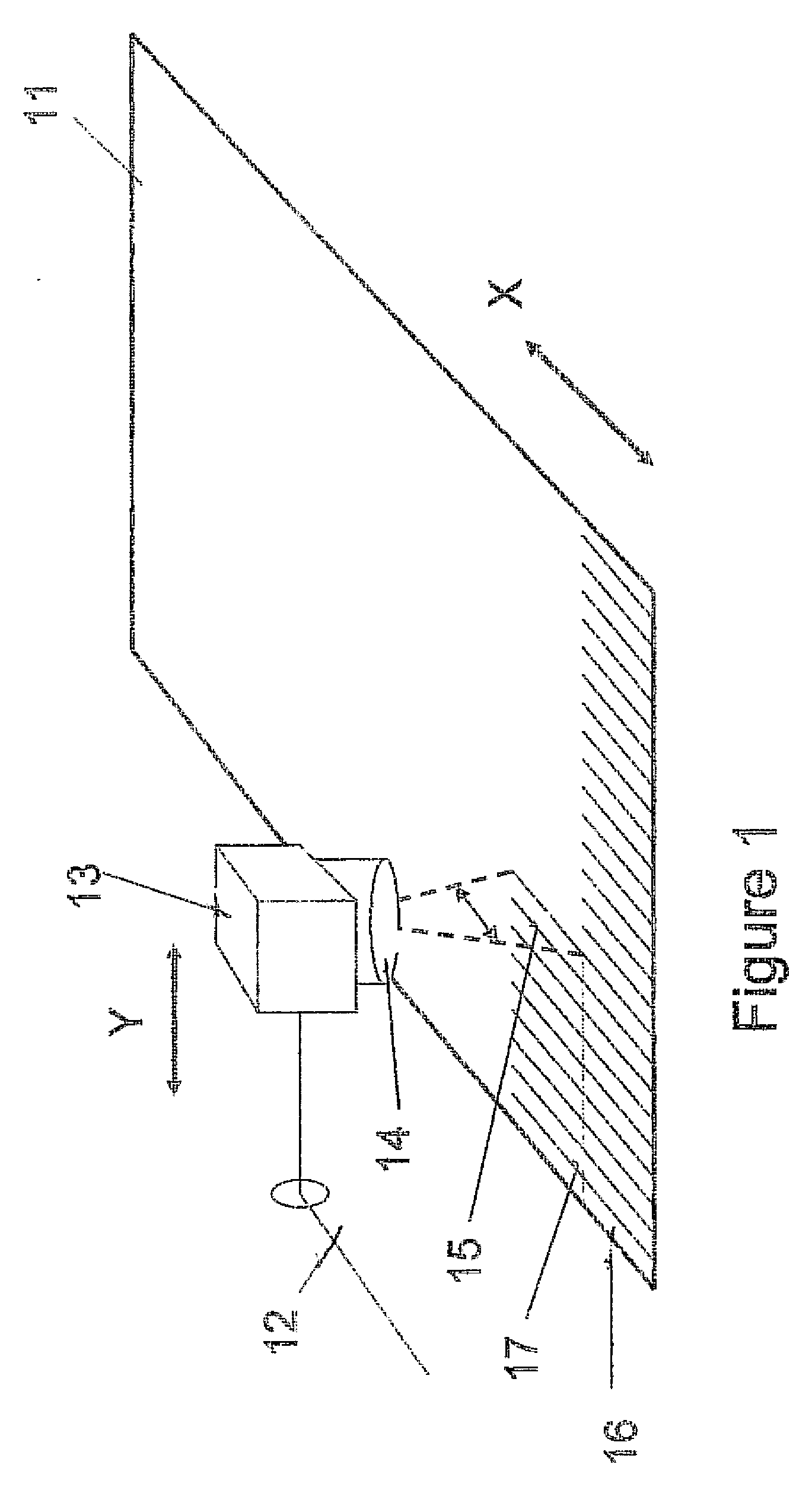
[0064]FIG. 1 A large flat solar panel 11 consisting of glass, metal or polymer substrate coated with an ITO or other conducting or semi-conducting layer or combination of layers is mounted on a stage system that allows it to move in one axis X. The requirement is to scribe multiple parallel lines in the coating running parallel to the long side of the rectangular panel in the X direction. The beam 12 from a laser is passed through a two-axis scanner unit 13 and is focussed by a lens 14 onto the surface of the panel in order to scribe lines 15 on the panel. The scanner unit is mounted on a moving carriage on a gantry over the panel so that it can move in the direction Y. Rows of scribe lines in the coating, running parallel to the X axis, are created in a series of bands 16 as shown, where the width of each band is a fraction of the total length of the panel. Each band is created by continuous movement of the scanner in the Y direction while the scanner unit is deflecting the beam ov...


PUM

PropertyMeasurementUnit
output voltagesaaaaaaaaaa
lengthsaaaaaaaaaa
speedaaaaaaaaaa

Abstract

A method for accurately laser scribing lines on a panel utilising a laser beam scanner unit (13) including an optical system and a scanner lens. The unit (13) moves a laser beam (12) in a first direction (X), to scribe sections of lines (15) on the panel (11) that are a fraction of the total line length required and then moving the unit (13) continuously with respect to the panel (11) in a second direction (Y), perpendicular to the first direction (X), to form a band (16) of scribe lines. The scanner unit (13) is positioned so that the starting position of scribe lines in each band next to be processed overlap exactly the finishing position ends of scribe lines in the last band that has been processed so that all scribe lines interconnect. The method repeats the using and moving steps to form a plurality of parallel bands of scribe lines which cover the area of the panel.

Description

[0001]This application is a continuation of U.S. application Ser. No. 11 / 762,910 filed Jun. 14, 2007 and claims priority from British Application Serial No. 0611738.6 filed Jun. 14, 2006.FIELD OF THE INVENTION[0002]This invention relates to a method for making multiple parallel laser scribes that are used to divide up large thin film solar panels and is based on creating parallel overlapping bands of small sections of the lines to be scribed by the use of scanner units. Such a method allows the scribes to be created quickly and accurately without high speed motion of the panel and permits a measurement system to be used that allows the position of secondary scribed lines to be placed very accurately with respect to previously scribed lines and permits compensation for irregularities in position caused by distortion of the panel.BACKGROUND OF THE INVENTION[0003]The use of lasers for scribing the thin layers found in solar panels to create and interconnect sub cells been well known fo...

Claims


Application Information

Patent Timeline
Patent Type & Authority Applications(United States)
IPC IPC(8): H01L31/042B23K26/00
CPCB23K26/032B23K26/04B23K26/0639B23K26/0648B23K26/0665H01L31/18B23K26/083B23K26/12B23K26/122B23K26/123B23K26/367B23K26/0807B23K26/064B23K26/082B23K26/1224B23K26/364B23K26/36B23K26/08
Inventor BANN, ROBERT
Owner OERLIKON SOLAR AG (TRUEBBACH)
Why Eureka
Try Eureka