
Refractive index measuring apparatus

a technology of index measuring apparatus and refractive index, which is applied in the direction of measurement devices, phase-affecting property measurements, instruments, etc., can solve the problems of difficult control methods, inability to measure, and the optical element which is a measurement target needs to be broken and polished, etc., to achieve the effect of convenient measuremen

Inactive Publication Date: 2011-03-03
PANASONIC CORP
View PDF4 Cites 17 Cited by
  • Summary
  • Abstract
  • Description
  • Claims
  • Application Information

AI Technical Summary

Benefits of technology

[0037]By using the present invention, a refractive index distribution of the test object can be easily measured without breaking the test object.

Problems solved by technology

However, in the conventional method in which the angle of deviation is measured, a test object needs to be processed in a predetermined shape and thus there is an issue that an optical element which is a measurement target needs to be broken and polished.
In addition, in the method in which a test object is immersed in a matching liquid whose refractive index is substantially equal to that of the test object, measurement can be performed without breakage, but non-uniformity of the refractive index of the matching liquid causes large error, causing an issue that a control method therefor is difficult.
Furthermore, the test object is narrowed to a range where the refractive index of the matching liquid is present, and many of matching liquids themselves are harmful to the environment and the human body, causing an issue that the convenience of measurement is impaired.

Method used


Image

  • Refractive index measuring apparatus
  • Refractive index measuring apparatus
  • Refractive index measuring apparatus

Examples


first embodiment

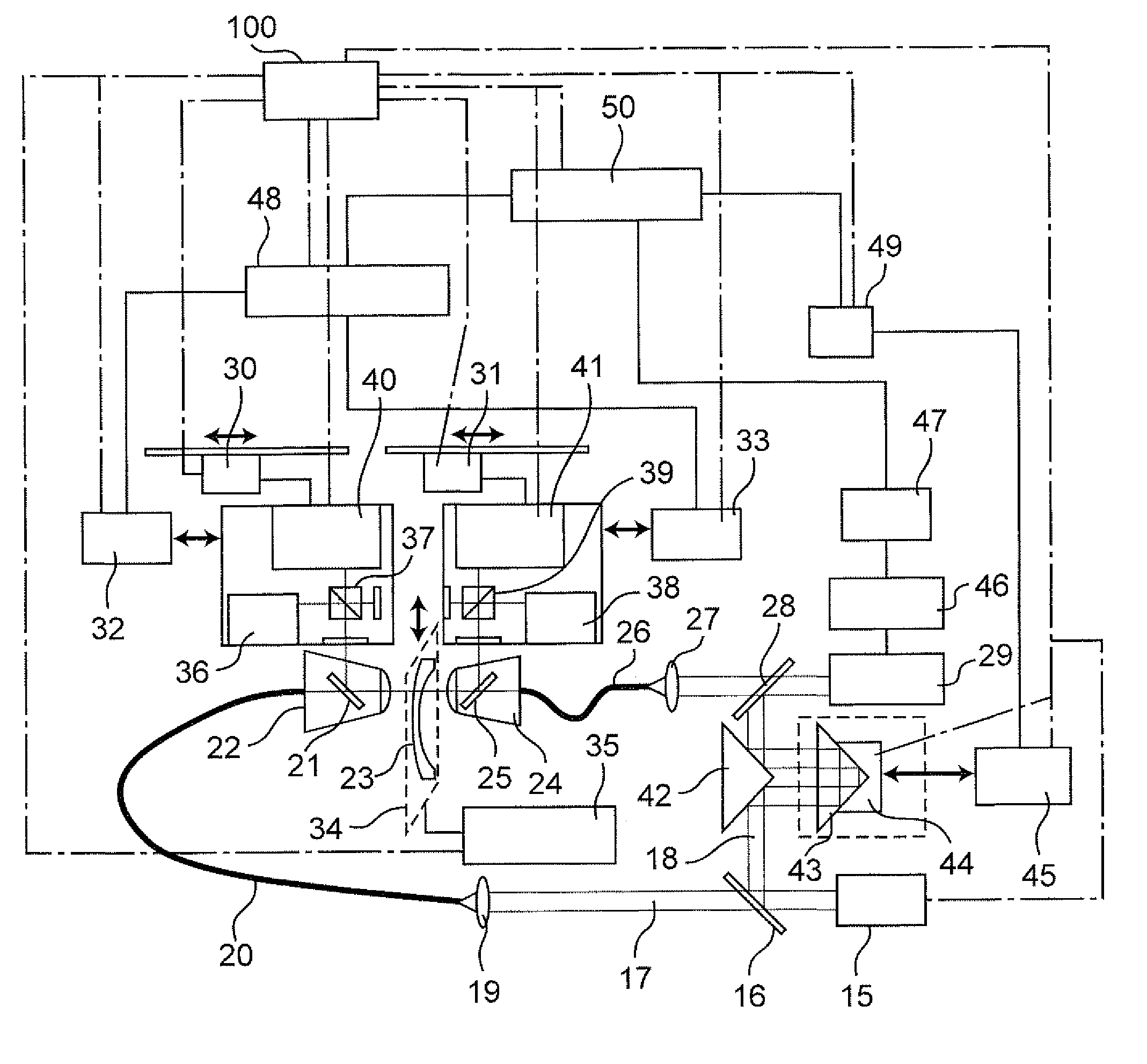
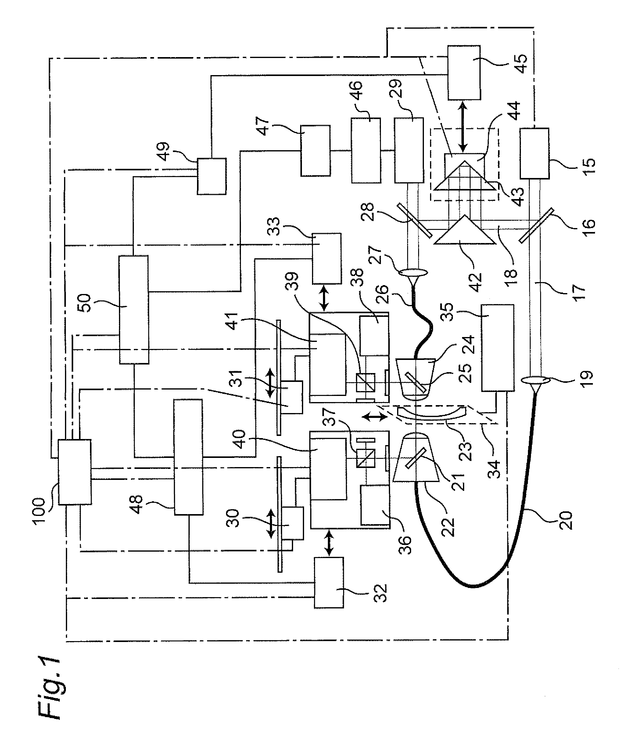
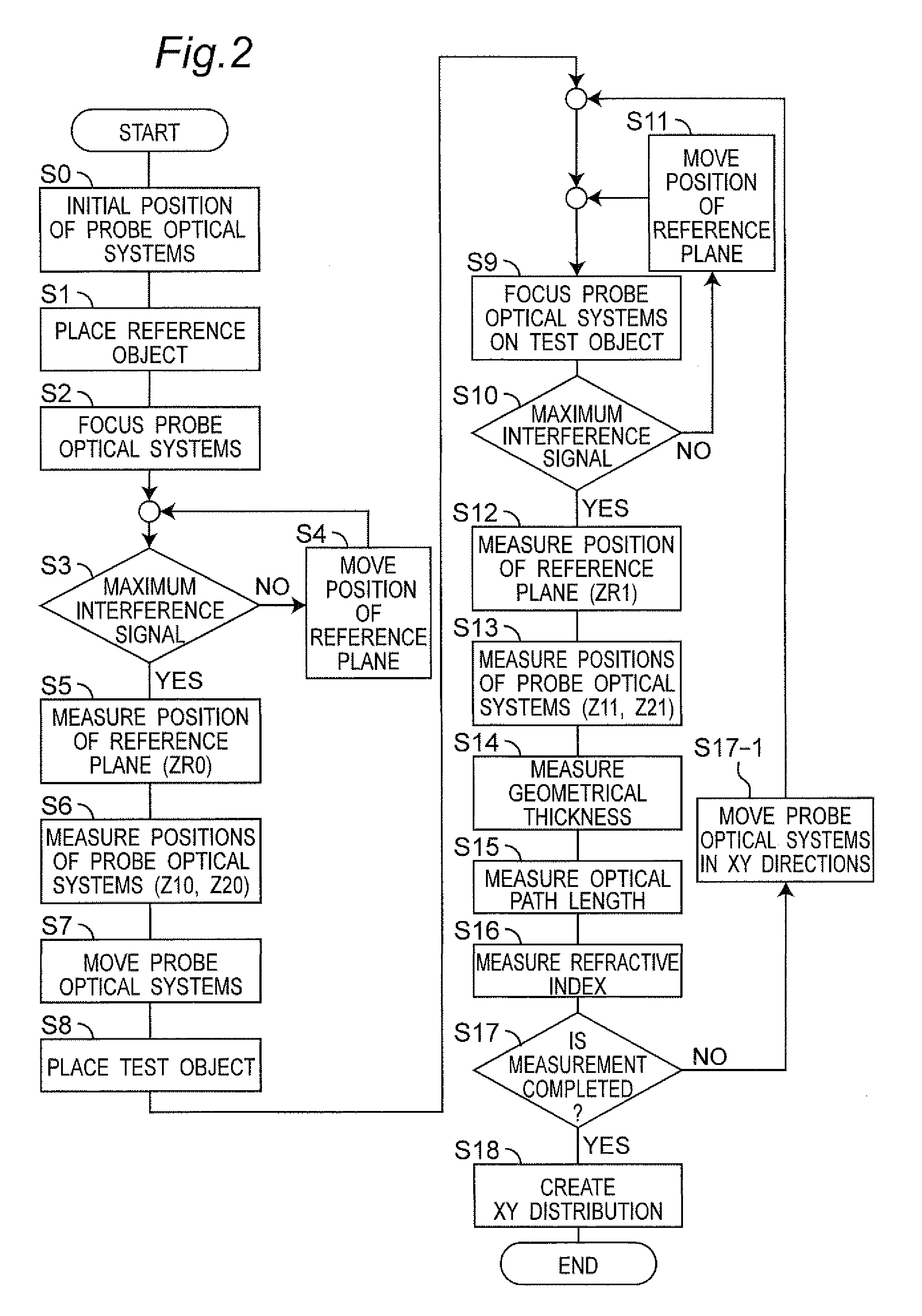
[0050]FIG. 1 is a conceptual configuration view of a refractive index measuring apparatus in a first embodiment of the present invention. FIG. 2 is a flowchart of refractive index measurement in the first embodiment. Note that a refractive index distribution of a test object 23 which is an optical member can be automatically measured by a control unit 100 controlling the respective operations of a light source 15, driving units 30, 31, 35, and 44, a refractive index calculating unit 50, a computing unit 48, a computing unit 49, an interference signal computing unit 47, a length measuring machine 45, a length measuring machine 32, a length measuring machine 33, a focus detecting unit 40, a focus detecting unit 41, etc., which are described below.

[0051]In FIG. 1, a beam emitted from the light source 15, typified by an SLD (Super Luminescent Diode), which emits low coherent light is split by a beam splitter 16 into test light 17 and reference light 18.

[0052]The test light 17 enters a f...


PUM


Abstract

By using two probe optical systems for measurement by disposing the probe optical systems with a test object sandwiched therebetween, an optical path length of light transmitted through the test object which is identified locally is calculated using an interference signal thereof. In addition, a geometrical thickness of the same part is calculated by measuring positions of the probe optical systems, whereby two calculated values are obtained. Based on the values and a calculated value for a reference object, a refractive index distribution of the test object is obtained.

Description

TECHNICAL FIELD [0001]The present invention relates to a refractive index measuring apparatus suitable to measure a refractive index distribution of an optical member such as an aspherical, spherical, or curved lens.BACKGROUND ART[0002]For an optical element to be used for digital copying or digital cameras, there is a molded lens.[0003]The molded lens is superior in the fabricability of an aspherical lens to a polished glass lens and is low in cost, but has an unstable side that non-uniformity is likely to occur in the refractive index distribution inside the lens, depending on the molding conditions. The non-uniformity of the refractive index inside the lens greatly affects the optical characteristics of the lens, which may cause degradation in image forming performance.[0004]Because of this, to stabilize the quality of molded lenses, a distribution of refractive indices needs to be measured with high accuracy.[0005]In recent years, a GRIN (GRadient-INdex) lens in which a refracti...

Claims


Application Information

Patent Timeline
IPC IPC(8): G01N21/41
CPCG01M11/0228
Inventor KUSAKA, YUSUKETAKECHI, YOHEIFUKUI, ATSUSHIHAMANO, SEIJITAKATA, KAZUMASA
Owner PANASONIC CORP
Learn More