Zoom lens and image pickup apparatus including the same

Inactive Publication Date: 2011-03-03
CANON KK
View PDF4 Cites 20 Cited by
  • Summary
  • Abstract
  • Description
  • Claims
  • Application Information

AI Technical Summary

Benefits of technology

[0007]According to the present invention, it is possible to obtain a zoom lens that allows a good image to be easily ob

Problems solved by technology

Unless these structures are properly set, it is difficult to obtain the above-described advantages.
For this reason, the moving amount of the first lens unit for zooming increases, and it is therefore difficult to reduce the thickness of the camera.
Further, sinc

Method used


Image

  • Zoom lens and image pickup apparatus including the same
  • Zoom lens and image pickup apparatus including the same
  • Zoom lens and image pickup apparatus including the same

Examples


first embodiment

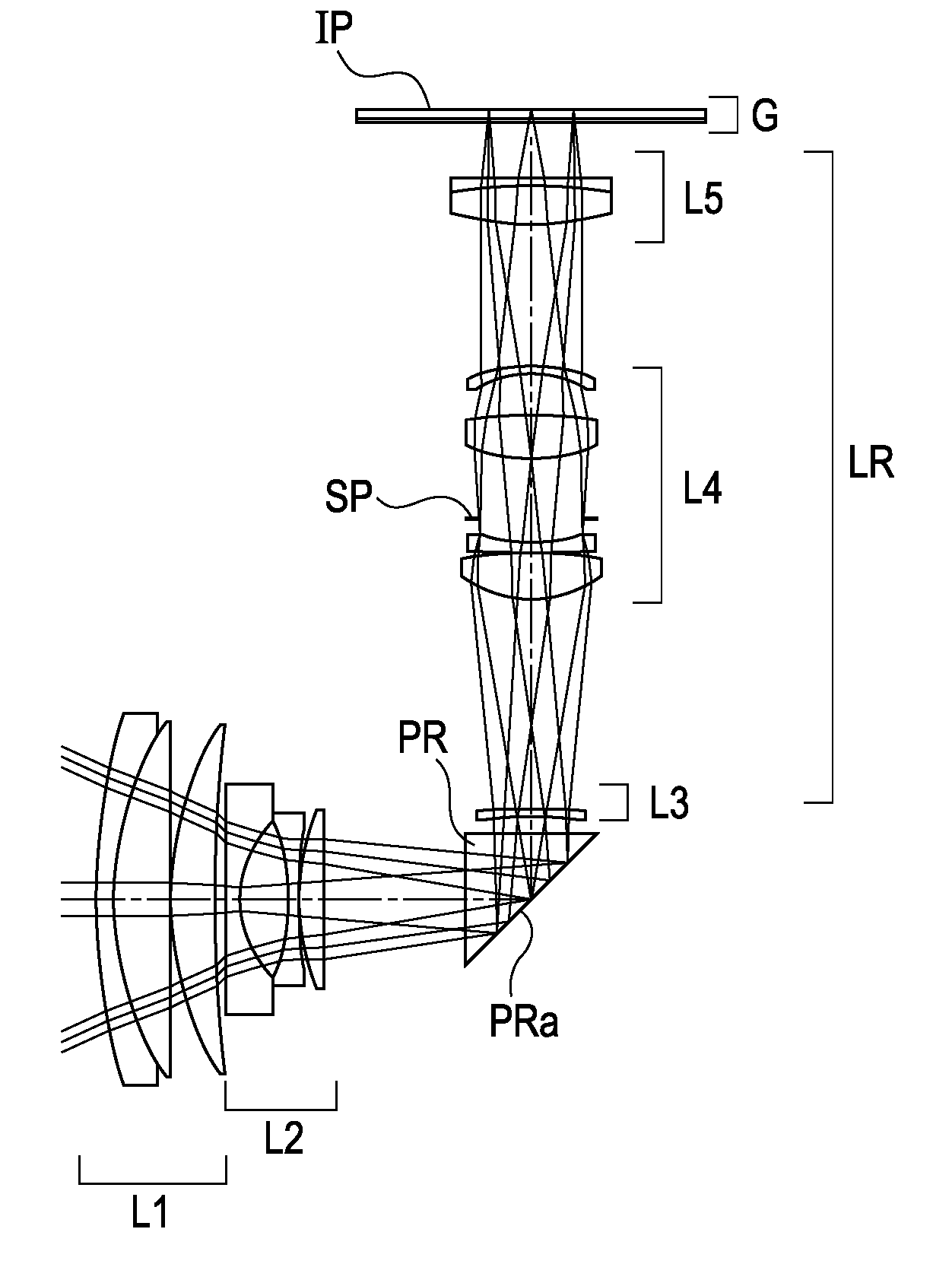
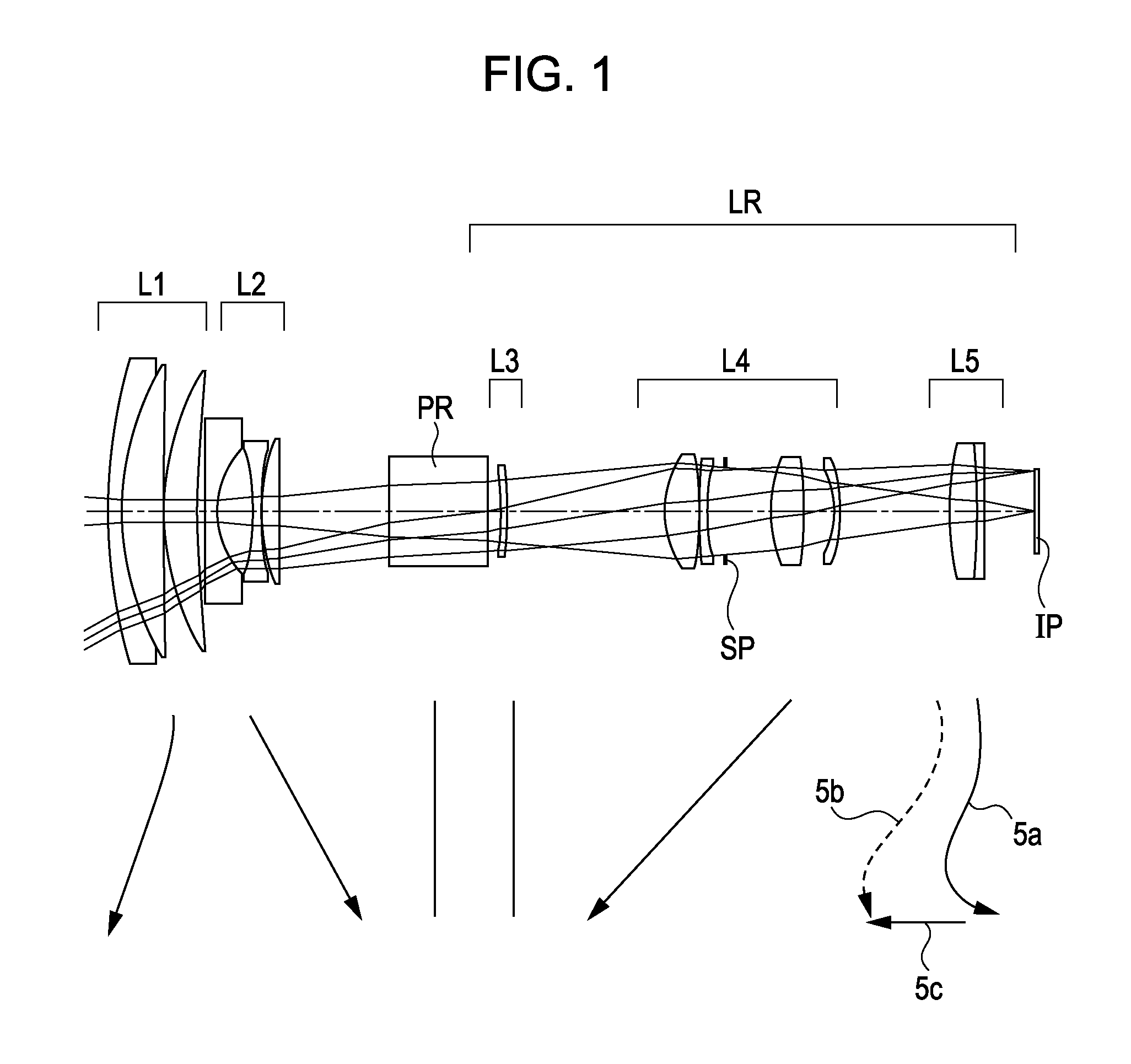
[0038]A description will be given of a lens configuration of a zoom lens of the first embodiment shown in FIG. 1. The zoom lens of the first embodiment includes, in order from the object side to the image side, a first lens unit L1 having a positive refractive power, a second lens unit L2 having a negative refractive power, a reflecting prism PR, and a rear group LR that are arranged along an optical axis of the zoom lens. The rear group LR includes a third lens unit L3 having a negative refractive power, a fourth lens unit L4 having a positive refractive power, and a fifth lens unit L5 having a positive refractive power. In the reflecting prism PR, a reflecting surface is provided to bend the optical path of light from the object. For zooming, the reflecting prism PR and the third lens unit L3 are fixed (do not move). While the third lens unit L3 is fixed during zooming in the first embodiment, it may be moved towards the object side during zooming from the wide angle end to the te...

second embodiment

[0039]A description will be given of a lens configuration of a zoom lens of the second embodiment shown in FIG. 3. The zoom lens of the second embodiment includes, in order from the object side to the image side, a first lens unit L1 having a positive refractive power, a second lens unit L2 having a negative refractive power, a reflecting prism PR, and a rear group LR. The rear group LR includes a third lens unit L3 having a negative refractive power, a fourth lens unit L4 having a positive refractive power, a fifth lens unit L5 having a negative refractive power, and a sixth lens unit L6 having a positive refractive power. In the reflecting prism PR, a reflecting surface is provided to bend the optical path from the object. For zooming, the reflecting prism PR, the third lens unit L3, and the fifth lens unit L5 are fixed. During zooming from the wide angle end to the telephoto end, the first lens unit L1 moves to the object side, the second lens unit L2 moves to the image side, and...

third embodiment

[0040]A description will be given of a lens configuration of a zoom lens of a third embodiment shown in FIG. 5. The zoom lens of the third embodiment includes, in order from the object side to the image side, a first lens unit L1 having a positive refractive power, a second lens unit L2 having a negative refractive power, a reflecting prism PR, and a rear group LR. The rear group LR includes a third lens unit L3 having a positive refractive power and a fourth lens unit L4 having a positive refractive power. In the reflecting prism PR, a reflecting surface is provided to bend the optical path from the object. During zooming from the wide angle end to the telephoto end, the first lens unit L1 and the third lens unit L3 move to the object side, and the second lens unit L2 moves to the image side. To correct image plane variation due to zooming, the fourth lens unit L4 moves to the object side along a convex path. The reflecting prism PR is fixed for zooming. When the image taking dista...


PUM


Abstract

A zoom lens includes, in order from an object side to an image side, first and second lens units respectively having positive and negative refractive powers, a reflecting prism for bending an optical path, and a rear lens group including lens units. At least the first and second lens units move for zooming. During retraction into a storage state, the prism moves to a position different from a position in an image taking state, and at least a part of the first and second lens units is retracted into a space formed by movement of the prism. Thicknesses of the first and second lens units, a moving amount of the first lens unit during zooming from a wide angle end to a telephoto end, a focal length of the first lens unit, and a focal length of the entire zoom lens at the telephoto end are set properly.

Description

BACKGROUND OF THE INVENTION[0001]1. Field of the Invention[0002]The present invention relates to a zoom lens suitable for use as an imaging optical system in an image pickup apparatus such as a video camera, a digital still camera, a broadcast camera, or a silver-halide camera.[0003]2. Description of the Related Art[0004]In recent years, an imaging optical system used in an image pickup apparatus has been requested to have a high zoom ratio and a compact size, and is particularly required to be formed by a zoom lens that allows thinning of a camera. A so-called retractable type zoom lens is known in which lens units are stored in a camera housing in a non-image-taking state by reducing gaps between the lens units to gaps different from those in an image taking state in order to achieve a smaller size of the camera and a higher zoom ratio of the zoom lens. Also, a so-called bent type zoom lens is known in which a reflecting prism for bending the optical axis of an imaging optical sys...

Claims


Application Information

Patent Timeline
IPC IPC(8): G02B15/14
CPCG02B15/177G02B15/143105
Inventor WADA, KENFUJISAKI, TOYOKATSU
Owner CANON KK
Why Eureka
Try Eureka