Parallel digital picture encoding

a digital picture and parallel video technology, applied in the field of video encoding, can solve the problems of slowing down the encoding process, affecting the encoding process, and requiring a high memory bandwidth,

Active Publication Date: 2011-03-03
SONY COMPUTER ENTERTAINMENT INC
View PDF15 Cites 72 Cited by
  • Summary
  • Abstract
  • Description
  • Claims
  • Application Information

AI Technical Summary

Problems solved by technology

Video signal coding tends to be a computationally intensive application requiring a high memory bandwidth.
However, due to the complexity of the encoding process it is difficult to optimize parallel video encoding for multi-processor platforms having more than two processor cores

Method used


Image

  • Parallel digital picture encoding
  • Parallel digital picture encoding
  • Parallel digital picture encoding

Examples


Embodiment Construction

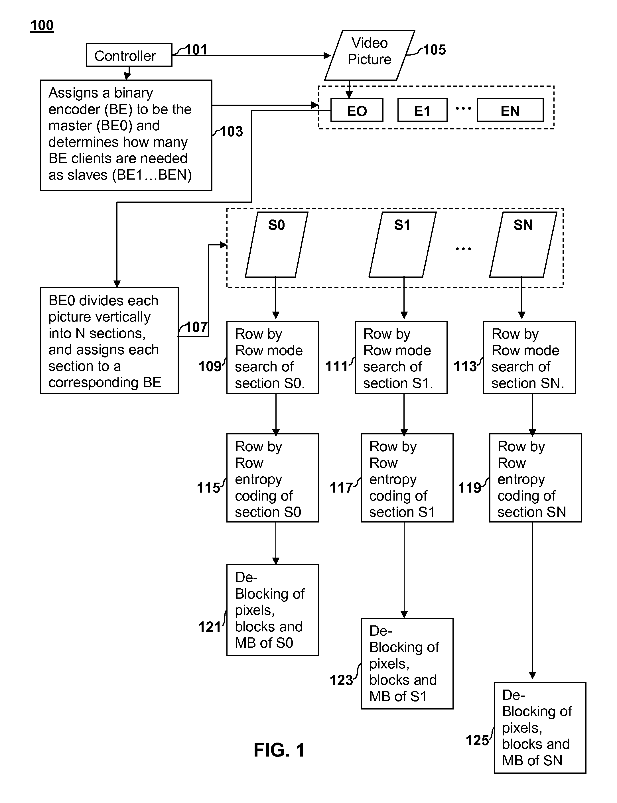
[0021]FIG. 1 is a flow diagram illustrating an example of parallel video encoding 100 that deals with the issue of data dependency according to an embodiment of the present invention. As used herein, parallel video encoding generally refers to encoding different sections of a video picture or different video pictures in such a way that process of encoding the respective sections or pictures overlap in time. In the prophetic example illustrated in FIG. 1, a controller 101 (e.g., a digital computer processor) initially chooses an encoder unit (labeled E0) from among a plurality of such units available in a processing system to act as the master / server encoder for the task of encoding one or more video pictures. The controller 101 also determines how many additional encoder units are needed as clients / slaves of the master / server encoder E0 to perform parallel encoding as indicated at 103. The client / slave encoder units are labeled as E1 . . . EN, where N represents the total number of ...


PUM


Abstract

Apparatus and Method for parallel digital picture encoding are disclosed. A digital picture is partitioned into two or more vertical sections. An encoder unit is selected to serve as a master and one or more encoder units are selected to serve as slaves. The total number of encoder units used equals the number of vertical sections. A mode search is performed on the two or more vertical sections on a row-by-row basis. Entropy coding is performed on the two or more vertical sections on a row-by-row basis. The entropy coding of each vertical section is performed in parallel such that each encoder unit performs entropy coding on its respective vertical section. De-blocking is performed on the two or more vertical sections in parallel on a row-by-row basis.

Description

CROSS REFERENCE TO RELATED APPLICATIONS[0001]This application is related to commonly-assigned co-pending U.S. patent application Ser. No. 12 / ______, which is filed the same day as the present application and entitled “PICTURE-LEVEL RATE CONTROL FOR VIDEO ENCODING” (Attorney Docket Number SCEA08073US00), the entire contents of which are incorporated herein by reference.[0002]This application is related to commonly-assigned co-pending U.S. patent application Ser. No. 12 / ______, which is filed the same day as the present application and entitled “SCENE CHANGE DETECTION” (Attorney Docket Number SCEA08074US00), the entire contents of which are incorporated herein by reference.[0003]This application is related to commonly-assigned co-pending U.S. patent application Ser. No. 12 / ______, which is filed the same day as the present application and entitled “UTILIZING THRESHOLDS AND EARLY TERMINATION TO ACHIEVE FAST MOTION ESTIMATION IN A VIDEO ENCODER” (Attorney Docket Number SCEA08078US00), t...

Claims


Application Information

Patent Timeline
IPC IPC(8): H04N7/26H04N7/32
CPCH04N19/00569H04N19/50H04N19/176H04N19/147H04N19/61H04N19/86H04N19/103H04N19/109H04N19/174H04N19/436H04N19/11
Inventor WANG, JASON N.KRISHNAN, RATHISHKUTNER, MICHAELMEHTA, MILANHUANG, CHENGLUO, YIBRELIN, JON
Owner SONY COMPUTER ENTERTAINMENT INC
Why Eureka
Try Eureka