

Imaging Device And Playback Device
a technology of a playback device and an imaging device, which is applied in the direction of stereophonic circuit arrangements, frequency response correction, television systems, etc., can solve the problems of not being able to obtain audio in keeping with the operator's intentions
- Summary
- Abstract
- Description
- Claims
- Application Information
AI Technical Summary
Problems solved by technology
Method used
Image

Examples
example 1
[0048]An explanation will be made with reference to diagrams of an embodiment that have implemented present invention in imaging devices, including digital cameras and digital video cameras that allow for recording and playback of audio and images. These imaging devices may be devices that can take video or devices that can take still images.
[0049](Configuration of the Imaging Device)
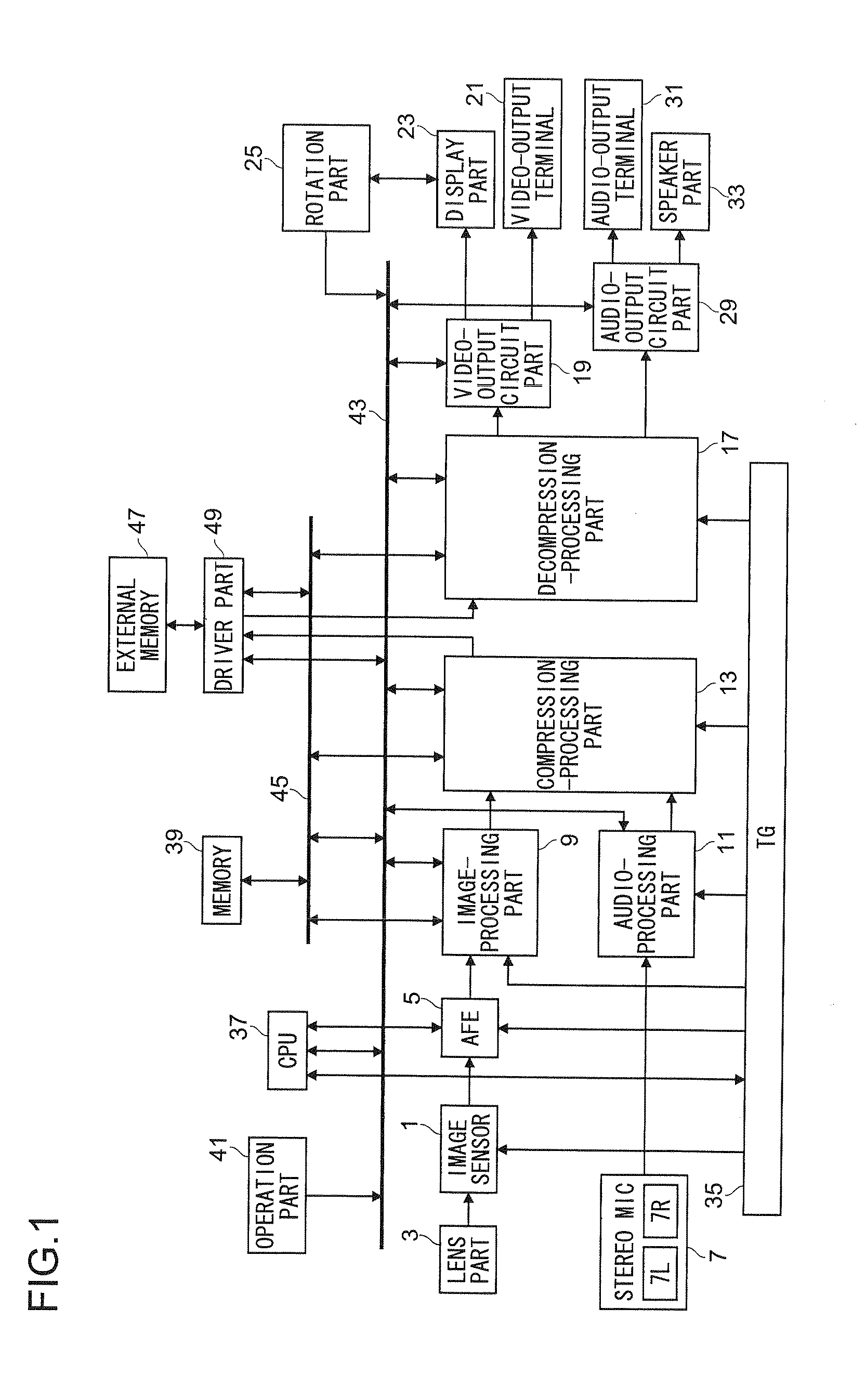
[0050]FIG. 1 is a block diagram that shows an outline of the internal configuration of the imaging device according to an Example 1 of the present invention. The imaging device of FIG. 1 is equipped with an image sensor (solid-state imaging element) 1 such as a charge coupled device (CCD) or complementary metal oxide semiconductor (CMOS) that converts incident light to an electric signal; a lens part 3 that has a zoom lens to form an optical image of the subject on the image sensor 1, a motor to change the focus distance of the zoom lens, that is to say, the optical zoom factor, and a motor to match the...
example 2
[0101]In Example 1, we presented an imaging device of the configuration shown in FIG. 1 as an example and explained the audio-processing method of the present invention, but the audio-processing method of the present invention may be used in playback devices that allow for audio and video output, such as DVD players and video decks that connect to liquid crystal displays and plasma displays, without being limited to imaging devices. FIG. 15 shows, as an example, a playback device that is provided with an audio-processing device (equivalent to audio-processing part 11) to conduct the audio-processing method of the present invention.
[0102]The playback device shown in FIG. 15 is, in the same manner as the imaging device shown in FIG. 1, provided with driver part 49; decompression-processing part 17; video-output circuit part 19; video-output terminal 21; display part 23; audio-output circuit part 29; audio-output terminal 31; speaker part 33; TG 35; CPU 37; memory 39; manipulation part...
example 3
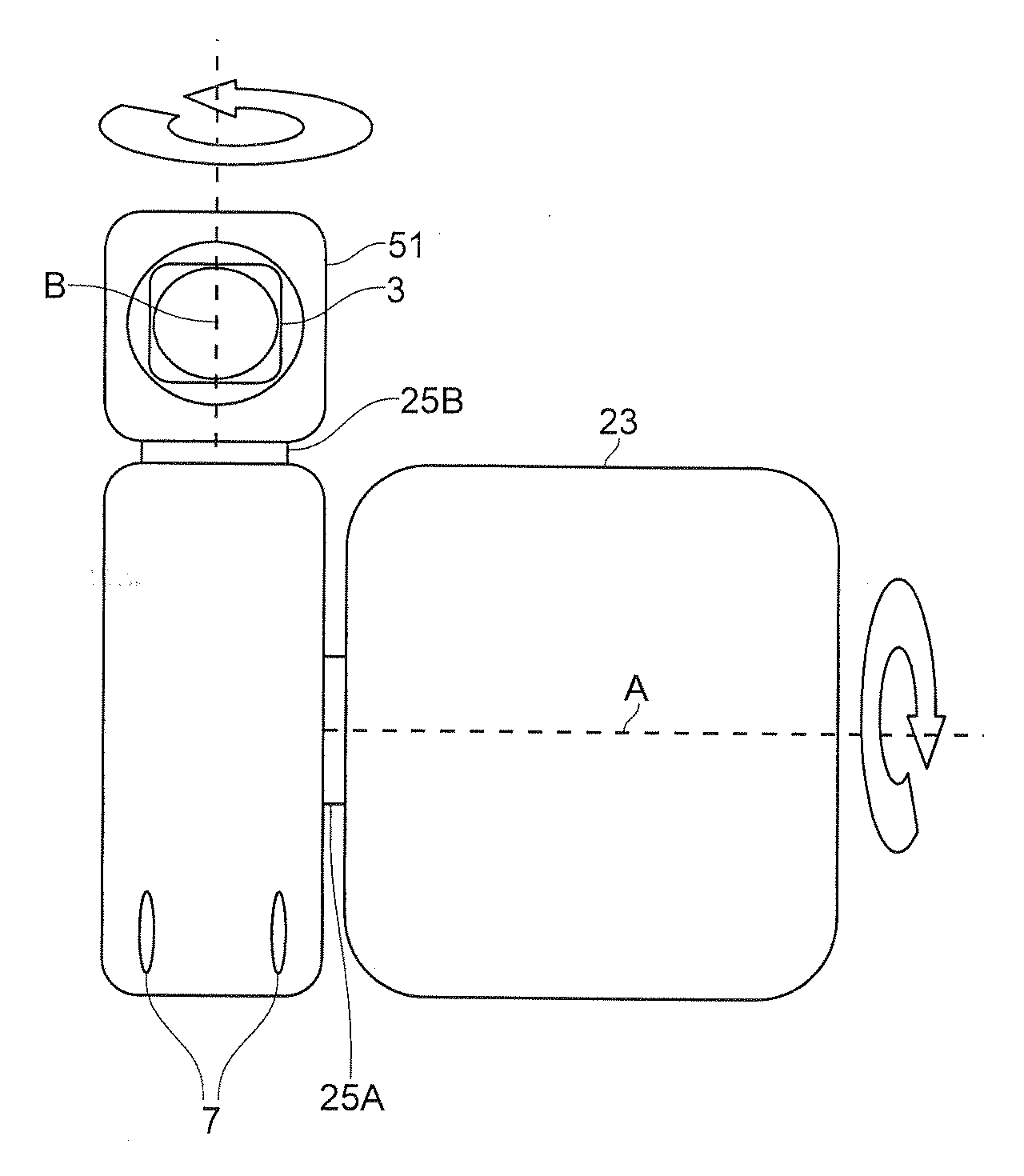
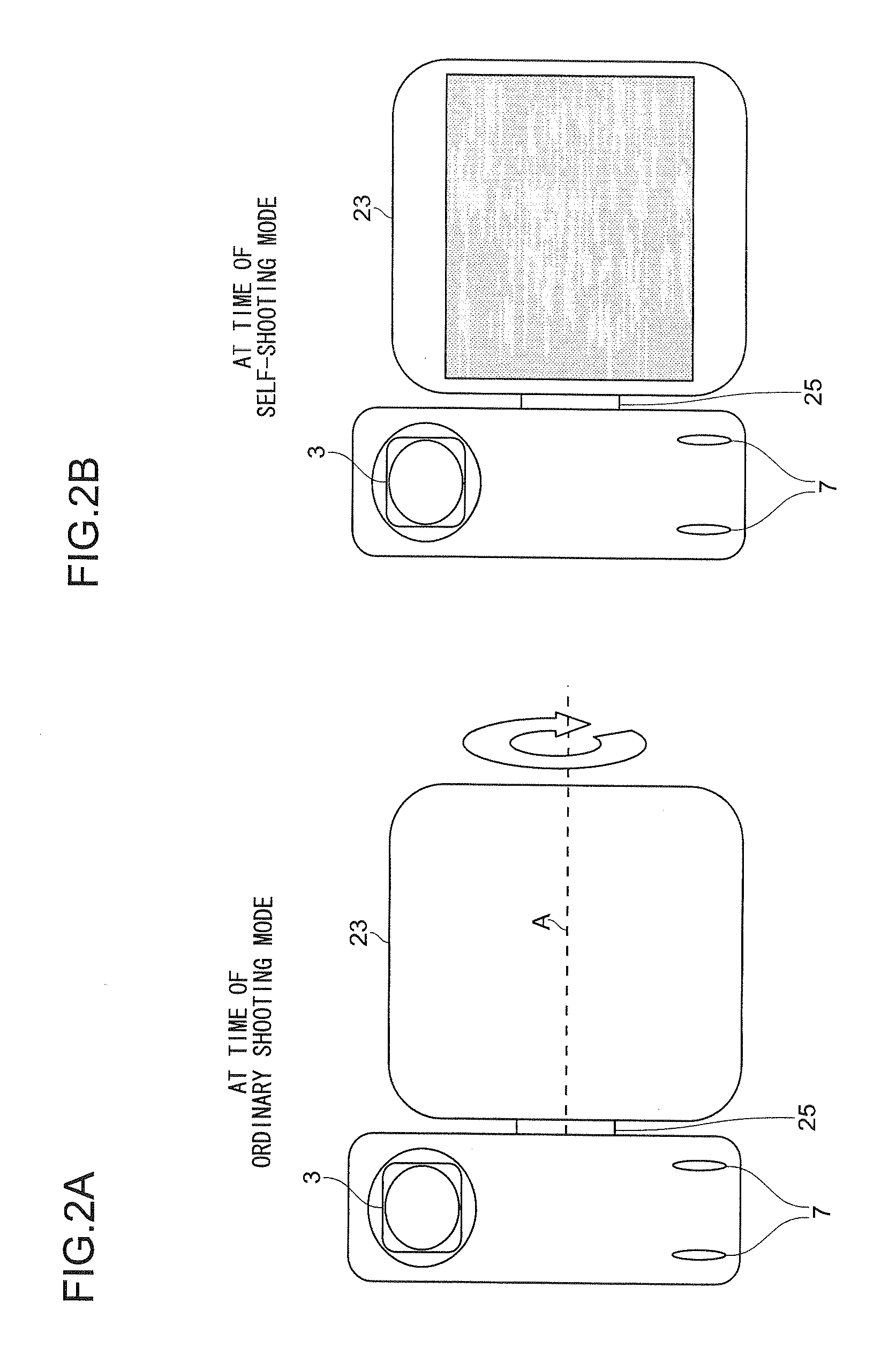
[0105]For Example 1, we provided an example in which we implemented the present invention in an imaging device in which display part 23 could be rotated, but the configurations of imaging devices in which the present invention can be implemented are not limited to this example. Specifically, it would be possible to implement the present invention in imaging devices in which a member other than display part 23 rotates. To start, we will provide an explanation with reference to figures of an example in which we have implemented the present invention in an imaging device in which display part 23 and optical-system members, such as the image sensor 1 and lens part 3 (hereinafter, noted as imaging part 51) are individually rotatable, presenting it as Example 3.
[0106]FIG. 16 is a block diagram that shows an outline of the internal configuration of the imaging device of this example and it is equivalent to FIG. 1 shown in Example 1. In addition, FIG. 17 is an illustration showing an outlin...
PUM
 Abstract
Description
Claims
Application Information