Control unit having a device for optical data transmission

Inactive Publication Date: 2011-03-03
ROBERT BOSCH GMBH
View PDF5 Cites 2 Cited by
  • Summary
  • Abstract
  • Description
  • Claims
  • Application Information

AI Technical Summary

Benefits of technology

[0004]It is also advantageous that a module is designed as an integrated expansion module (IEM), which is supplied with power via a plug connection connected to the mounting plate. The individual modules may be exchanged as, desired, as it is not necessary for the pin number of the module to be limited. The control unit may be designed to be more flexible without significant additional costs, as the modules may be replaced by other modules without additional changes on the mounting plate. Power may be supplied to the individual modules in a very simple manner through the plug connection. The optical transmission connection makes it possible, for example, to exchange the module on the first mounting plate without difficulty and replace it with another module. If the pin number of the module situated on the first mounting plate is changed, the optical connection makes it unnecessary to make a change on the second mounting plate. Due to the optical connection, additional functions of the module situated on the first mounting plate or printed circuit board do not require changes on the optical transmission device. As already mentioned, compared to metallic connections, any amount of information may be forwarded. As a result, the construction and assembly costs of the control unit may be reduced.
[0005]Accor

Problems solved by technology

As a result, information is no longer transmitted between individual mo

Method used


Image

  • Control unit having a device for optical data transmission
  • Control unit having a device for optical data transmission

Examples


Embodiment Construction

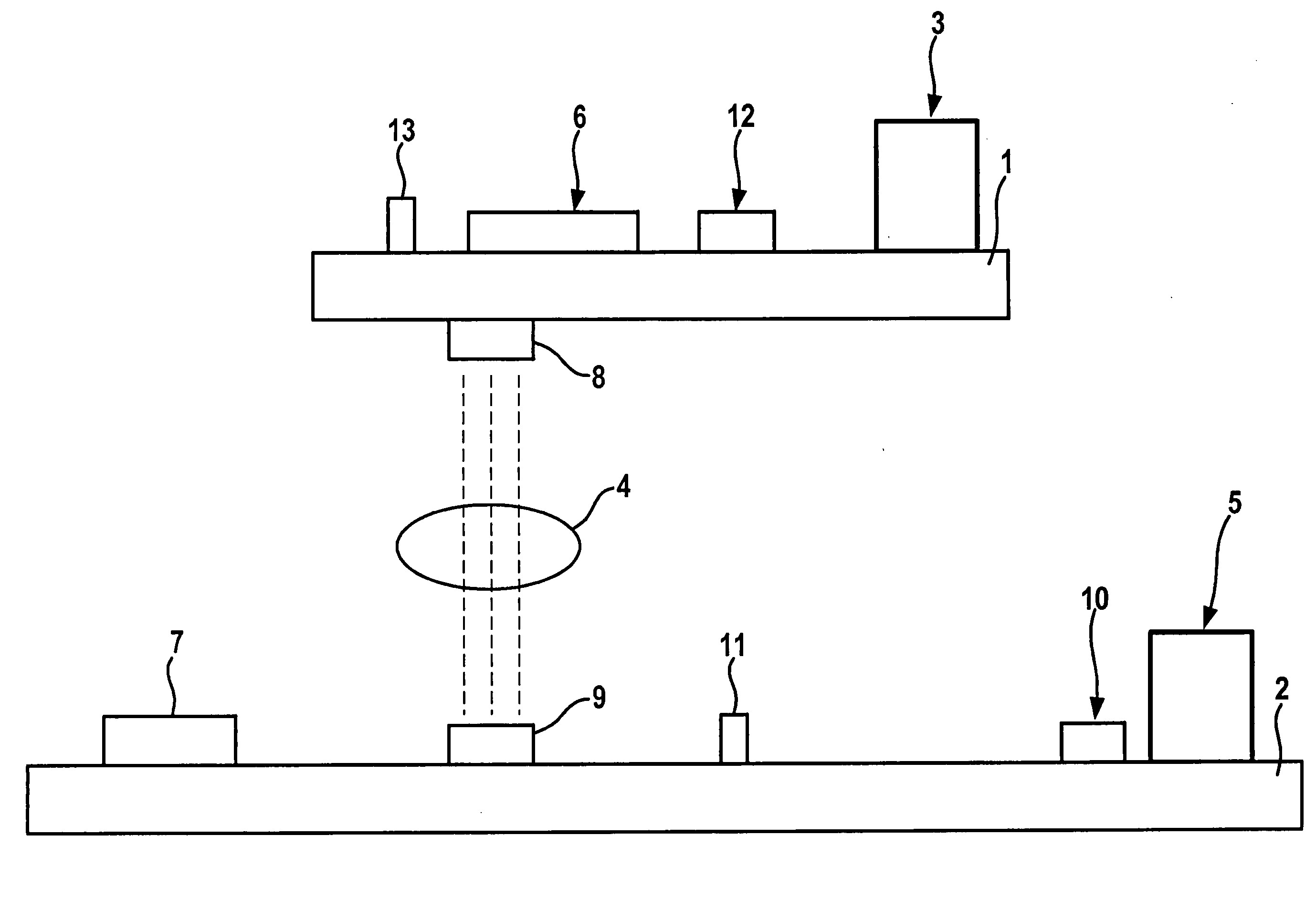
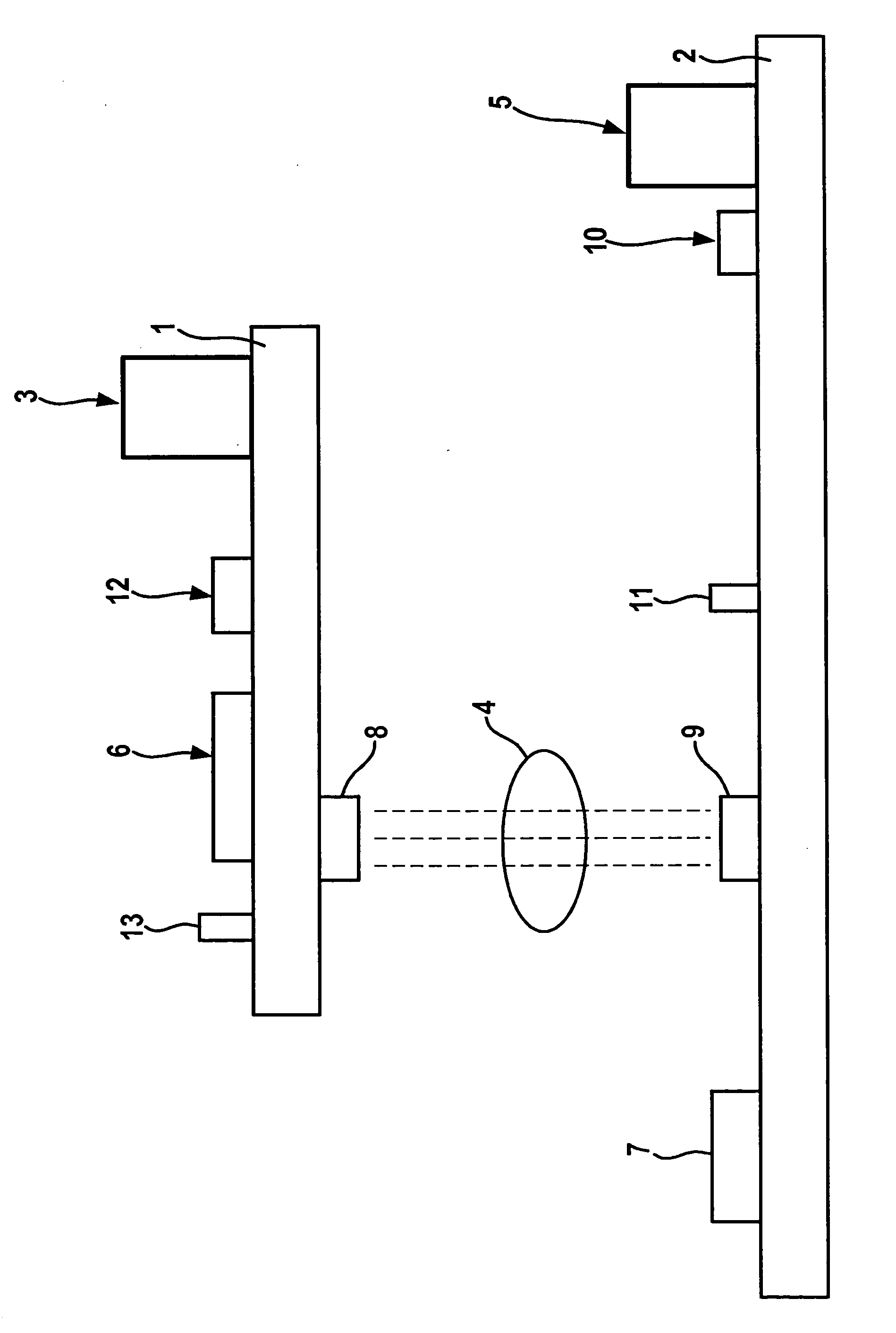
[0012]The drawing shows that a first mounting plate 1 and a second mounting plate 2, also referred to below as a printed circuit board, are operatively connected via an optical transmission device 4 instead of a metallic connection, and the information or data transfer takes place via this optical transmission device 4. Optical transmission device 4 may be designed as a laser or infrared device or the like and is therefore significantly more flexible and less susceptible to interferences than the metallic connections used to this date and is in particular insensitive to shocks occurring during operation. The optical transmission device described according to the present invention is able to transport data unidirectionally from the components of the first mounting plate (IEM) to the second mounting plate as well as exchange data starting from second mounting plate 2 to first mounting plate 1, depending on the purpose of the application. For the data transfer, optical transmission dev...


PUM


Abstract

The invention relates to a control unit comprising a data transmission device, comprising at least one module (6) which is arranged on a mounting plate (1) and actively connected to a power supply system. The data are as least forwarded to a second module (7) which is arranged on a second mounting plate (2). Data transmission from the first module (6) to the at least one additional module (7) proceeds via an optical transmission device (4).

Description

FIELD OF THE INVENTION[0001]The present invention relates to a control unit including a data transmission device, having at least one module situated on a mounting plate and being operatively connected to a voltage supplyBACKGROUND INFORMATION[0002]In connection technology, data are transmitted between modules on different printed circuit boards via metallic connections. Typically, one connection is used per signal. This results in high costs for final assembly. Moreover, metallic connections are exposed to severe stresses when vibrations occur on the control unit and are consequently easily interference-prone. Furthermore, when metallic connections are used, the transmission speed between the individual modules is limited and they are furthermore very susceptible to electromagnetic couplings and the malfunctions associated with them.SUMMARY OF THE INVENTION[0003]The exemplary embodiments and / or exemplary methods of the present invention provides that the data are transmitted from o...

Claims


Application Information

Patent Timeline
IPC IPC(8): H04B10/10H04B10/114
CPCH04B10/1143H05K1/141H05K1/0274
Inventor STUMPF, TOBIASSCHWARZE, KLAUS
Owner ROBERT BOSCH GMBH
Why Eureka
Try Eureka