Running wheel for suction machine

A technology of working wheel and suction machine, which is applied to components, mechanical equipment, machines/engines, etc. of pumping devices for elastic fluids. It can solve problems such as difficulty in fixing, reduce manufacturing costs, save plastics, and improve machinery /Effect of mechanical properties

Inactive Publication Date: 2007-05-23
DURR DENTAL GMBH & CO KG
View PDF1 Cites 3 Cited by
  • Summary
  • Abstract
  • Description
  • Claims
  • Application Information

AI Technical Summary

Problems solved by technology

However, this will cause difficulties in fixing on the shaft

Method used


Image

  • Running wheel for suction machine
  • Running wheel for suction machine
  • Running wheel for suction machine

Examples


Embodiment Construction

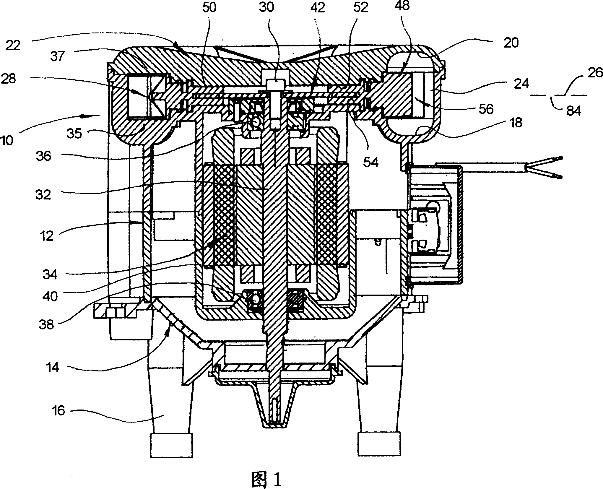
[0029] FIG. 1 shows a side channel suction machine with a housing generally indicated at 10 . The housing comprises a two-piece substantially cylindrical middle shell part 12 which is screwed to a lower shell part 14 supported by feet 16 .

[0030] The upper end of the middle shell portion 12 is tapered and defines a groove portion 18 which, together with an aligned groove portion 20 in the upper shell portion 22, defines a working space 24 . The working space has a circumferentially increasing cross-section and is symmetrical about a median plane 26 .

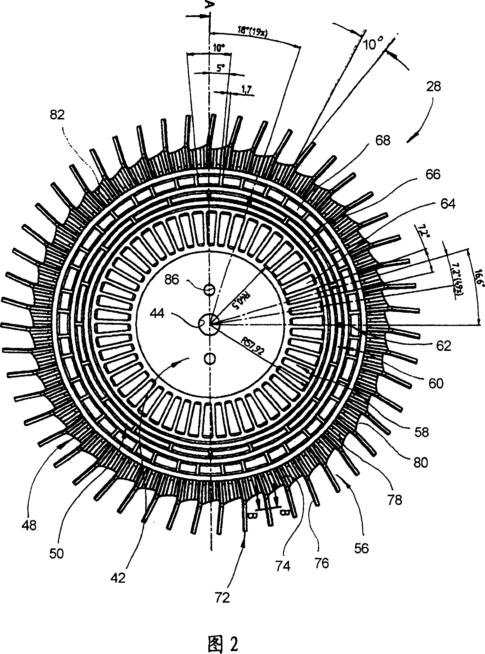
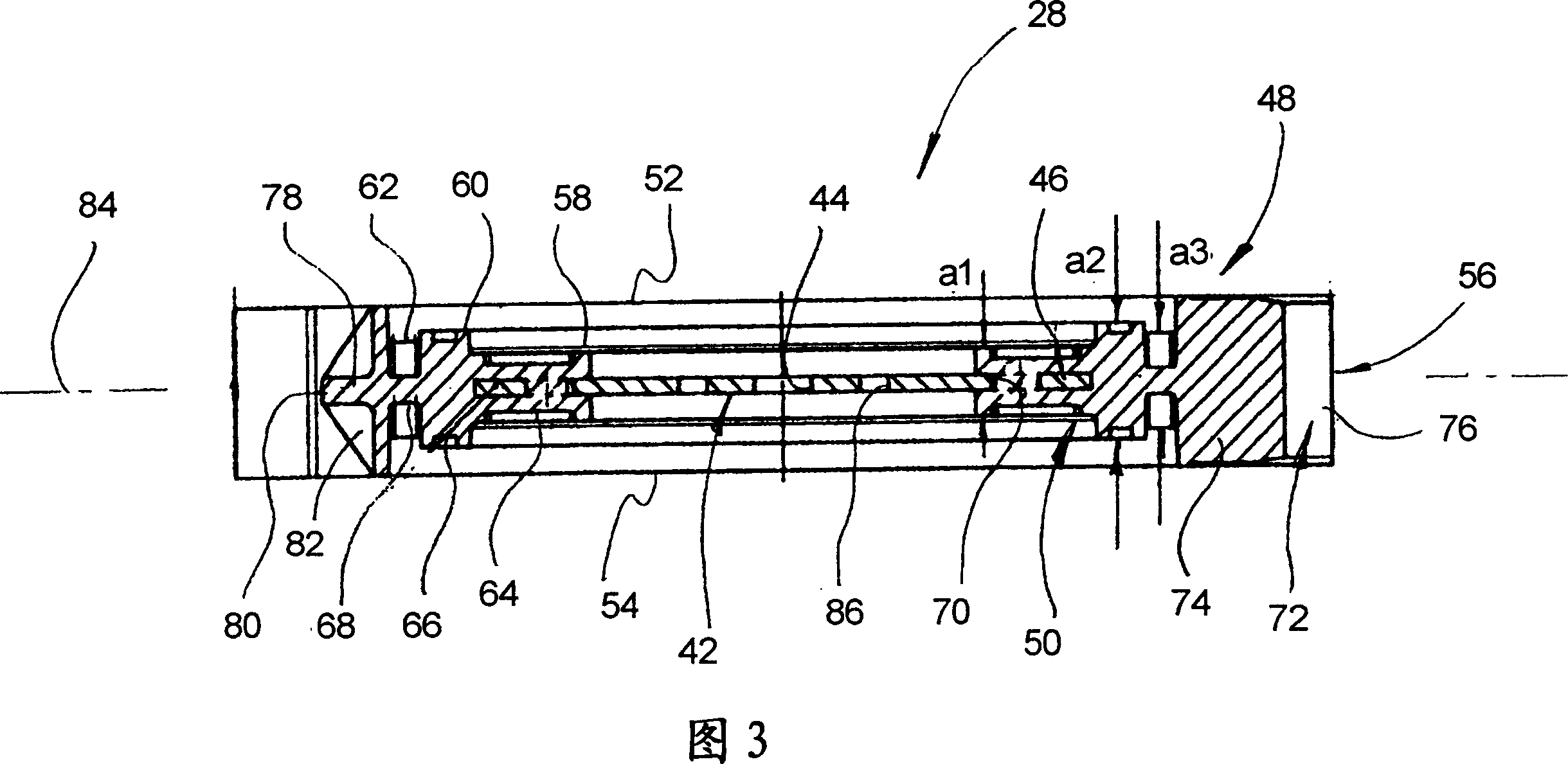
[0031] In the working space 24 a working wheel, indicated in its entirety at 28 , rotates and is firmly connected by means of screws 30 to the end of a motor shaft 32 , which belongs to the electric machine in its entirety at 34 . The motor shaft 32 is supported on bearings 36 , 38 supported by a motor housing 40 .

[0032] The access to the workspace 24 can be conceived as opening into the workspace in front of the drawing ...


PUM


Abstract

The invention relates to an impeller 28 for a side channel sucking machine including a hub component 42 which can be coupled with a drive shaft. A guide ring 50 manufactured out of plastic is formed and attached to the hub component 42 manufactured out of metal. Many blades 72 distributed in a circumference direction are attached on the same.

Description

technical field [0001] The invention relates to an impeller for a suction machine according to the preamble of claim 1 . Background technique [0002] The operating principle of a side-channel suction machine is known, for example, from DE 4128150 A1. The groove-shaped spaces of the impeller bounded by the blades together with the channels of the fan casing extending in the circumferential direction form a conveying device for the gaseous medium, through which the gaseous medium is conveyed from the gaseous medium in a spiral swirl The inlet of the suction machine is conveyed to the outlet. The impeller of this suction machine rotates at a high rotational speed (3000 rpm in practice). The impeller must therefore be well balanced and, moreover, it must run with a small sealing gap in the housing. [0003] The impeller of the side channel machine described in DE 4128150 A1 is a cast part which is machined with high precision. Such castings are heavy, so large imbalances ma...

Claims


Application Information

Patent Timeline
Patent Type & Authority Applications(China)
IPC IPC(8): F04D29/02F04D29/30A61C17/00
CPCF04D23/008F04D29/281F04D17/168
Inventor E·农嫩马赫
Owner DURR DENTAL GMBH & CO KG
Why Eureka
Try Eureka