
Flushable device for measuring through-flow processes of fluids

A fluid and flow-through technology, which is applied in the direction of measuring devices, measuring flow/mass flow, volume change compensation/correction devices, etc., can solve problems such as gas blockage discharge, measurement errors, and problems, and achieve the effect of avoiding dead ends

Active Publication Date: 2019-08-23
AVL列表有限责任公司
View PDF8 Cites 0 Cited by
  • Summary
  • Abstract
  • Description
  • Claims
  • Application Information

AI Technical Summary

Problems solved by technology

[0007] However, it has been found that by this measure existing air plugs cannot be completely removed from the flow measuring device, but that they accumulate in various dead spaces of the device and at a certain point dissipate there, which subsequently leads to measurement errors
Especially in those measuring devices that work at higher pressures and whose positive displacement flowmeter is driven by an electric motor with a magnetic clutch interposed, problems arise due to gas plugs in the magnetic clutch

Method used


Image

  • Flushable device for measuring through-flow processes of fluids
  • Flushable device for measuring through-flow processes of fluids
  • Flushable device for measuring through-flow processes of fluids

Examples


Embodiment Construction

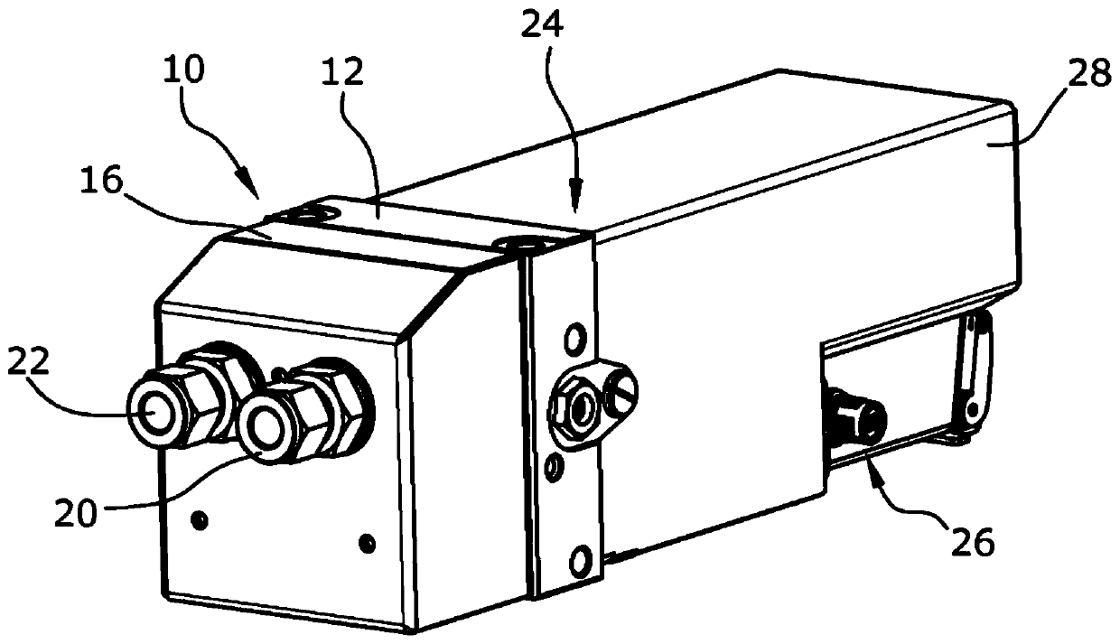
[0040] figure 1 A device according to the invention for measuring a time-resolved throughflow process is shown in . The device according to the invention has a housing 10 made of two parts, wherein a displacement flow meter 14 is arranged on a first housing part serving as a volume housing 12 and a second housing part serving as a piston housing 16 A differential pressure recorder 18 is arranged on the two housing parts. In addition, an inlet 20 and an outlet 22 are formed on the piston housing 16 . The drive unit 24 and the evaluation and control unit 26 of the positive displacement flowmeter 14 are arranged inside a housing 28 which is likewise fastened to the volume housing 12 like the piston housing 16 .

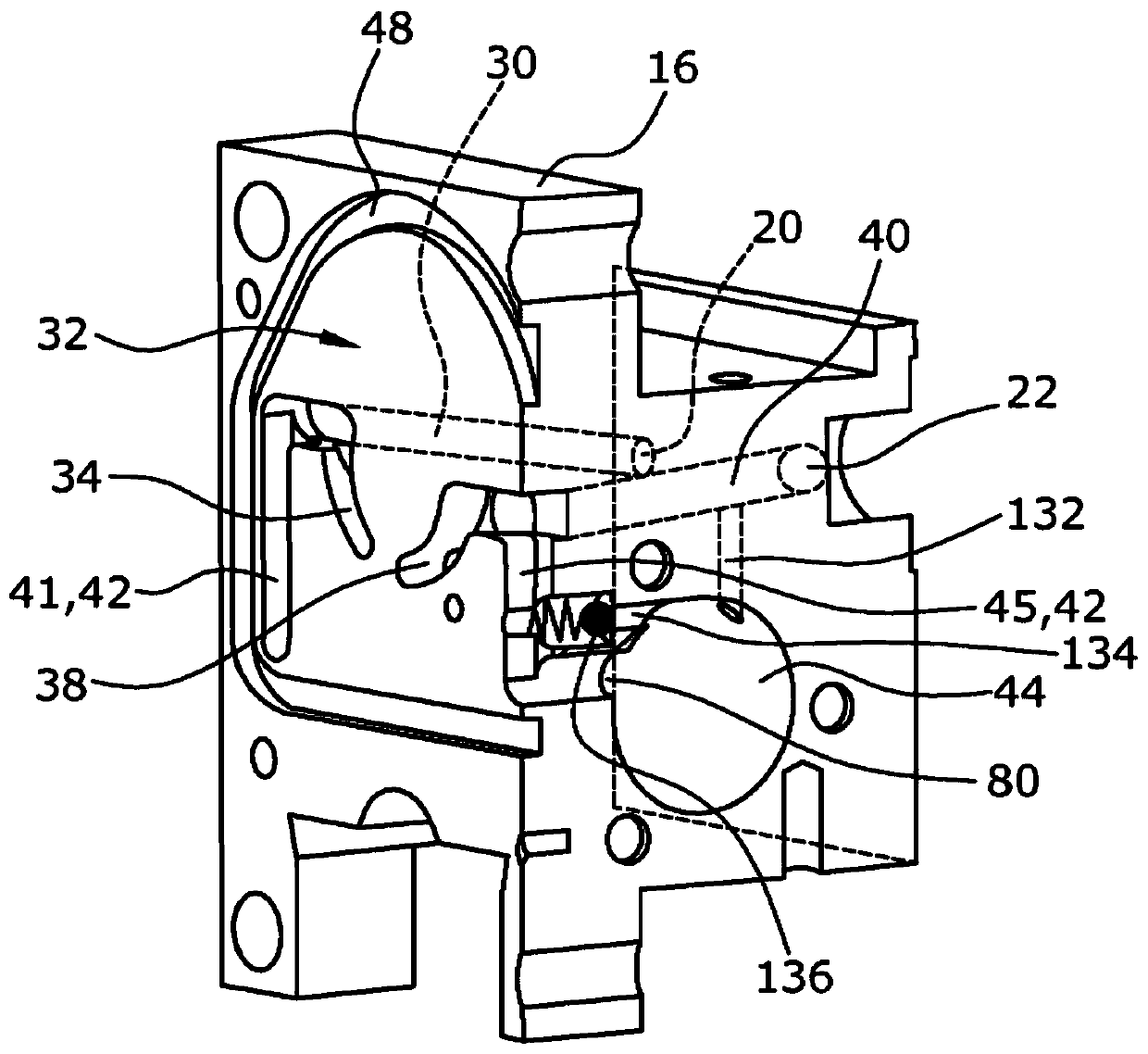
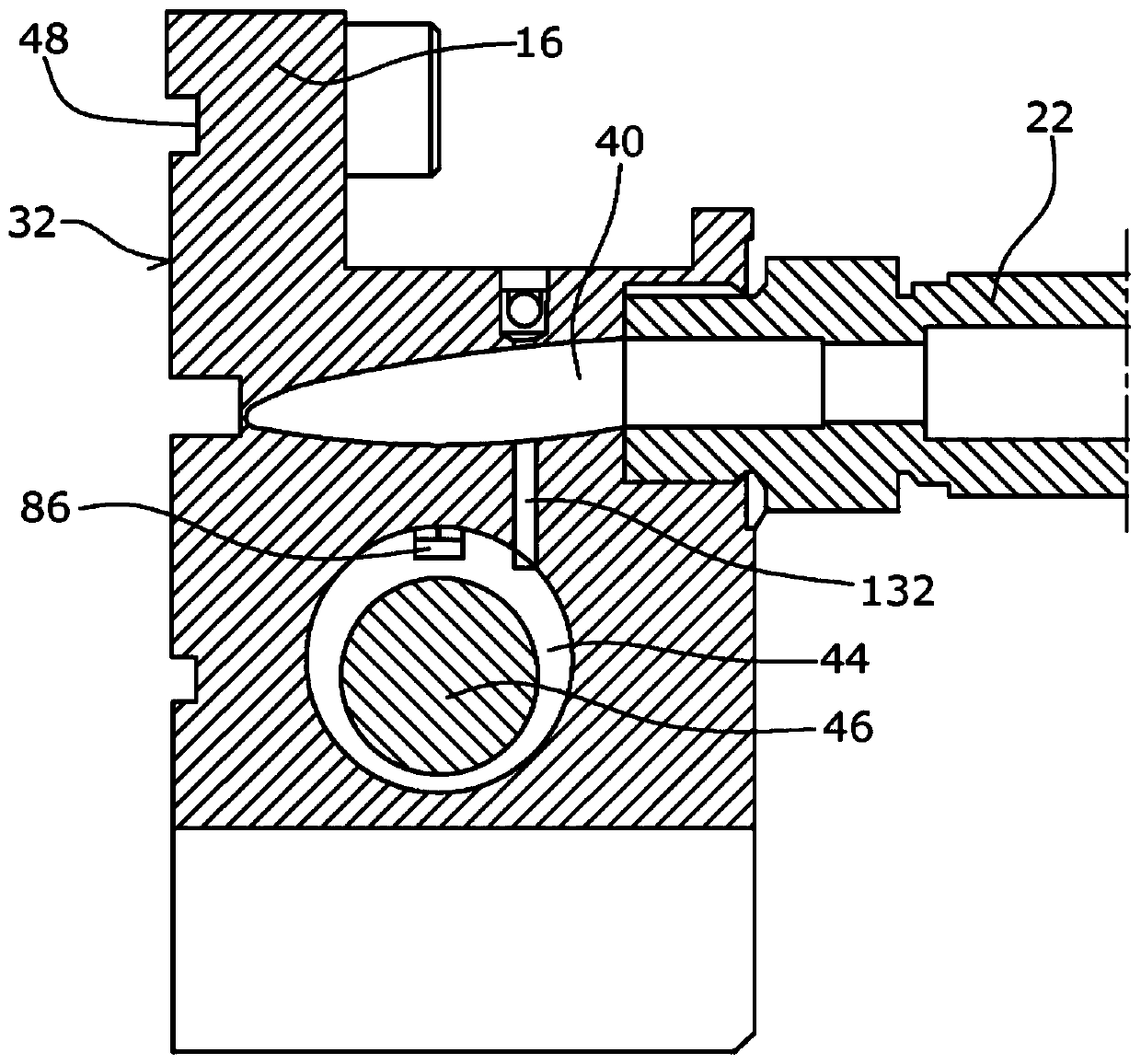
[0041] figure 2 Piston housing 16 is shown in . Fuel flows via the inlet 20 into an inlet channel 30 , which extends through the piston housing 16 to a wall 32 delimiting the end side of the piston housing 16 . Several further channels are milled into the wall 32 ....


PUM


Abstract

A device for measuring the flow process of a fluid, having an inlet (20), an outlet (22), a volumetric flowmeter (14) capable of being driven by a drive unit (24), the volumetric flowmeter (14) The extrusion chamber (36) is fluidly connected to the inlet (20) through the input channel (30) and is fluidly connected to the outlet (22) through the outlet channel (40), bypass (42), through the bypass (42) capable of bypassing the positive displacement flowmeter (14), the differential pressure recorder (18) arranged in the bypass (42), and the evaluation and control unit (26), through the evaluation and control A unit (26) is able to control a drivable positive displacement flow meter (14) as a function of the differential pressure acting on said differential pressure recorder (18). The inlet channel (30) and the outlet channel (40) are configured to rise in the flow direction of the fluid.

Description

technical field [0001] The invention relates to a device for measuring the flow process of a fluid, having an inlet, an outlet, a volumetric flowmeter that can be driven by a drive unit, the extrusion chamber of the volumetric flowmeter is connected to the inlet fluid through an input channel connected and fluidly connected to the outlet via a discharge channel, a bypass through which the volumetric flowmeter can be bypassed, a differential pressure recorder arranged in the bypass, and an evaluation and control unit through The evaluation and control unit is able to control the drivable positive displacement flow meter as a function of the differential pressure acting on the differential pressure recorder. Background technique [0002] Such devices have been known for many years and are used, for example, to measure injection quantities in internal combustion engines. [0003] An original version of this device for flow measurement has been described in document DE-AS 1 798...

Claims


Application Information

Patent Timeline
Patent Type & Authority Patents(China)
IPC IPC(8): F04C15/06F04C2/10F04C2/344G01F3/10G01F15/02
CPCG01F3/06G01F3/10G01F15/026F04C2/10F04C2/344F04C15/06F04C2220/24F04C2220/40
Inventor O.德尔施密特
Owner AVL列表有限责任公司
Learn More